Credentials — Restricted Content Enter your authorisation code to view this tab.
ACCESS DENIED — INVALID CODE
Aerospace · Engineering · Innovation
STEVE CLAMP
Aerospace Consultant Engineer
With decades of experience spanning military and commercial aviation, unmanned flight vehicles, aero engines, space launch systems, satellite architecture, and renewable energy engineering, Steve provides world-class consultancy at the intersection of aerospace innovation and practical engineering excellence.
▼ Explore Specialisations ▼
Steve
Aerospace Consultant Engineer
Steve is an engineer, pilot and businessman, with over 35 years of engineering experience spanning commercial aviation, military aviation, aero engines, missiles, rockets, space systems, lighter-than-air vehicles, alternative energy, and unmanned flight systems. Select a discipline below to explore his work.
35+ Years200+ ClientsBerlin · Derby · Scottsdale · Lake Tahoe
Areas of Expertise
Select a Discipline
01
✈️
Section One
Aircraft
Commercial & military aviation systems, aerodynamics, structural analysis
Academic credentials, professional certifications & industry recognition
→
Section 01 — Aircraft Systems
AIRCRAFT
Commercial · Military · General Aviation
Steve brings over 30 years of hands-on experience in aircraft design, stress and structural analysis, and certification. From narrow-body commercial jets to high-performance military platforms, his expertise covers the complete engineering lifecycle — from concept to airworthiness certification.
Across the aircraft programmes below, Steve's role typically spanned the full engineering lifecycle: design support, detailed stress analysis, development & qualification testing, and certification / permits to fly.
35+Years Experience
120+Aircraft Projects
18Certifications
12Countries
LARGE COMMERCIAL TRANSPORT
BOEING 747-8 INTERCONTINENTAL
Wide-body · Quad-engine · Long-haul
FAR 25CONVENTIONAL METALLIC STRUCTUREGEnx ENGINES
Canadair · Montréal · Business Jet Program
CANADAIR CHALLENGER CL-600 — WING STRESS ANALYSIS
Detailed Wing Stress Analysis · Empirical Methods · Pre-FEM Era
WING BOX
Detailed Stress
EMPIRICAL
Hand Methods
CL-600
Business Jet
CANADAIR · CL-600 CHALLENGER · MONTRÉAL
Wide-Body Cabin Business Jet · Twin Lycoming ALF 502
Foundational platform for the entire Challenger / Global / CRJ family
SUPERCRITICAL WINGT-TAILFAR 25 CERTIFIED
Steve's Contribution
On the Canadair CL-600 Challenger programme at Canadair's Montréal facility, Steve completed the detailed stress analysis of the wing using empirical methods — the structured hand-calculation techniques that defined airframe stress engineering before the widespread adoption of finite element analysis.
The work covered the wing box, spar caps and webs, ribs, and skin panels — sized against the full manoeuvre and gust envelope using established stress-engineering handbooks (Bruhn, Niu, Roark, ESDU and Lockheed/Boeing in-house manuals), beam-column and shear-flow analysis, classical buckling and post-buckling stability checks, and stress-concentration factors for every fastener row, cutout and load-introduction fitting. Fatigue and damage-tolerance assessment was carried out using S-N data and crack-growth methods to satisfy FAR 25 certification requirements.
The CL-600 Challenger went on to become the foundational platform for an entire family of derivatives — the Challenger 601 / 604, the Global Express, and the Canadair Regional Jet (CRJ) series — making this early wing-stress work an enduring contribution to one of the most successful business and regional jet families ever produced.
Wing Box Analysis
DETAILED STRESS
Spar caps, webs, ribs and skin panels sized against full FAR-25 manoeuvre and gust envelope.
Frame members & systems routing viewed from within the structure
Bulkhead 2598 — Forward
Station 2598 bulkhead forms the primary structural load path for the horizontal tail actuator. Steve's analysis covered the complete frame cross-section under combined internal pressure, fuselage bending, and shear loads per FAR 25.571 damage tolerance requirements.
Station 2598Pressure BoundaryFAR 25.571
Bulkhead 2464 — Aft
Station 2464 analysis addressed the complex load path redistribution around large cutouts and stiffened panel intersections. Stress concentration factors (K_t) at lightening hole edges and fastener rows were critical to demonstrating adequate fatigue life margins under FAA certification.
Station 2464Cutout K_tFatigue Margins
Lightening Holes & Stiffeners
Circular and rectangular lightening holes reduce frame weight while stiffener rings restore local shear stiffness. FEA analysis confirmed stress concentration factors and validated the stiffener sizing against ultimate and limit load FAR 25 requirements, preventing premature crack initiation.
Stress ConcentrationStiffener RingsFEA Validated
FAA Certification Analysis
Full compliance documentation produced for FAA DER review, including static strength substantiation, damage tolerance assessment, and inspection programme recommendations. Analysis to FAR 25.305 (strength), 25.307 (proof of structure), and 25.571 (fatigue & damage tolerance).
FAR 25.305FAR 25.571DER Review
747 Structural Integrity Program
The Boeing 747 fuselage structure is a masterclass in pressurised shell design — circular frames spaced at 20-inch intervals carry both hoop loads from pressurisation and bending/shear loads from flight and ground conditions. Steve's stress analysis of Bulkheads 2598 and 2464 contributed to the FAA certification evidence package, demonstrating structural integrity at limit loads (1.0×), ultimate loads (1.5×), and residual strength after assumed damage — supporting the 747's outstanding safety record across decades of commercial operation.
Boeing 747 Structural ProgramFAA Certification EvidenceLimit & Ultimate LoadResidual Strength
Boeing 787 Dreamliner · Section 48 · Composite Aft Fuselage
The Boeing 787 Dreamliner represented a generational step-change in commercial aircraft design — the first widebody airliner with a majority-composite primary structure, supplied by a globally distributed manufacturing network and assembled at Boeing Everett. Steve's engagement at Everett spanned the era when the 787 programme was ramping up alongside continuing 747-8 production, and his structural work touched components and methodologies shared between the two programmes.
Section 48 is the Boeing nomenclature for the 787's aft fuselage section — the empennage-supporting structure aft of the rear pressure bulkhead. As one of the first major composite primary structures to enter commercial service at scale, Section 48 demanded new analysis methods for impact damage tolerance, fastener bearing in composite laminate, lightning-strike protection and through-thickness load transfer at the metallic-to-composite interfaces.
The Dreamlifter — Boeing's modified 747-400 Large Cargo Freighter — was developed specifically to transport 787 sub-assemblies (composite fuselage barrels, wings, tail sections) between supplier sites in Italy, Japan and the United States and the final assembly lines at Everett and Charleston. The logistics architecture was as much an engineering achievement as the airframe itself.
EVERETT FINAL ASSEMBLY · ZA001 PROTOTYPE
787 Dreamliner on the Assembly Line
Composite fuselage barrels · final assembly · Boeing Everett
The 787 first flight was a tremendous success for the teams and the company. My time in Everett and Seattle was truly memorable, and I feel fortunate to have worked with such a first-class group of engineers.
COMPOSITE PRIMARY STRUCTURE
~50% Composites by Weight
Carbon-fibre-reinforced polymer barrel sections; titanium and Ti-Gr composite for high-load fittings.
SECTION 48 — AFT FUSELAGE
Empennage Support Structure
Carries horizontal and vertical stabiliser loads; engineered for damage tolerance and lightning-strike protection.
Note on photos: Team photos from the 787 programme — including the Section 48 engineering team, the Dreamlifter at Everett, and the Blended Split Winglet Future Development team — are featured in the Memorable People tab, where the focus is on the engineers and colleagues behind the work rather than the airframe itself.
Aerodynamic Design
Expertise in wing design, high-lift systems, drag reduction, and transonic/supersonic flow regimes. Proficient in both analytical and computational methods including panel codes, vortex lattice methods, and full 3D CFD.
CFD AnalysisWing ShapingHigh-Lift Devices
Structural Engineering
Advanced finite element analysis of primary and secondary aircraft structures. Fatigue and damage tolerance assessments compliant with FAR Part 25, JAR, and EASA CS-25 regulations.
FEA / FEMFatigue AnalysisCS-25 Compliance
Systems Integration
Flight control systems, hydraulics, pneumatics, and avionics integration. Experience with fly-by-wire architectures and redundant safety-critical system design to DO-178C and ARP4754A standards.
Fly-by-WireDO-178CAvionics
Performance & Certification
Aircraft performance calculations, flight manual data, and regulatory compliance. Supported type certificate and supplemental type certificate applications with major airworthiness authorities globally.
STC / TCEASA / FAAFlight Testing
Notable Projects & Programs
Steve's aircraft engineering portfolio spans wide-body long-haul freighter conversions, regional turboprop performance optimisation, and military unmanned aerial systems. He has served as chief aerodynamicist on two new type design programmes and provided independent technical authority reviews for three major airline acquisition programmes. His work on composite primary structures has reduced structural weight by up to 18% on relevant airframes.
Feature Program
Aeritalia · Naples, Italy
ATR 42
Doors & Fuselage Structural Stress Analysis
ATR 42
Turboprop
JAR-25
Cert. Basis
Naples
Aeritalia
REGIONAL TURBOPROP
ATR 42 AERITALIA
Naples, Italy · Fuselage & Door Stress Analysis
PRESSURISED FUSELAGEDOOR CUTOUTSJAR-25 CERTIFIED
Steve performed the structural stress analysis of the ATR 42 fuselage, door cutouts, and door structures while working with Aeritalia in Naples, Italy — one of the two founding partners of the ATR consortium (alongside Aérospatiale, France). The ATR 42’s pressurised fuselage presents complex stress distributions around door apertures, requiring rigorous analysis of hoop stress interruption, corner reinforcement doublers, and door surround frames to meet JAR-25 airworthiness certification requirements.
Von Mises Stress Analysis — ATR 42 Fuselage & Door Cutouts
348 MPa
Peak σ_vm
0 MPa
Min σ_vm
Linear Static
Analysis Type
JAR-25
Certification
DOOR FRAME PEAKSFUSELAGE SKINLOW STRESS ZONES
Von Mises stress computed from linear static analysis. F-WMTO registration. Inset panels show exterior and interior views of front passenger door (left) and aft passenger door (right) — peak stress concentrations visible at door frame corners and hinge/latch fittings.
Boeing Commercial Airplanes · New Aircraft Program
December 15, 2009 · Paine Field, Everett, Washington
An exciting day for all who worked on Boeing's first all-composite aircraft
BOEING EVERETT · 787 PROGRAM TEAM
Boeing 787 Dreamliner — Program Team, Everett
Wing to Body Integration
CFRP
Composite Structure
Analysis of wing to body joint and sloping pressure desk
Section 45 — Sloping Pressure Deck
Steve completed the detailed stress and finite element analysis of Section 45 — the structurally complex sloping pressure deck forming the wing-to-body joint. This critical region transfers the massive wing bending and shear loads into the fuselage while maintaining pressure vessel integrity across the cabin floor.
Section 45Pressure DeckWing-Body Joint
All-Composite Airframe
The Boeing 787 Dreamliner was the world's first commercial transport aircraft built predominantly from carbon fibre reinforced polymer (CFRP). The composite fuselage and wing structure required new analytical methods — classical metallic analysis tools had to be adapted and validated for orthotropic CFRP laminates.
CFRPComposite AnalysisOrthotropic
FEA Methodology
Detailed finite element modelling of the Section 45 pressure deck, including ply-by-ply composite layup, fastener load transfer, and non-linear contact between the wing stub and fuselage frames. Analysis performed to FAR 25 limit and ultimate load requirements.
Ply-by-Ply FEAFastener LoadsFAR 25
First Flight — December 2009
The 787 Dreamliner's first flight from Paine Field, Everett on December 15, 2009 was a momentous occasion for all who contributed to this groundbreaking programme. For Steve and the structural analysis team, seeing the aircraft fly for the first time was the culmination of years of detailed, painstaking engineering work.
On the Airbus A380 New Feature Program, Steve completed the detailed stress analysis of the wing and wing high-lift devices — covering the leading-edge slats, trailing-edge flaps and their support tracks, carriages and actuation kinematics. The high-lift system on the A380 carries the heaviest variable aerodynamic loads of any commercial aircraft in service, and each fitting was checked for ultimate, limit and residual strength under the full CS-25 manoeuvre and gust envelope.
In parallel, Steve led the fatigue and fracture analysis of the front and rear spars. The spars are the primary span-wise load-carrying members of the wing box, transferring bending and shear from the outer wing into the centre wing box and fuselage. The analysis combined classical S-N fatigue, strain-life methods, and linear elastic fracture mechanics (LEFM) crack-growth predictions at every fastener row, joggle and run-out — establishing inspection intervals and damage-tolerant life consistent with the A380's design service goal.
The deliverables fed directly into the airworthiness submission package and supported the EASA / FAA Type Certification process for the world's largest passenger aircraft.
Wing Stress Analysis
FULL ENVELOPE
Ultimate · limit · residual strength checks on wing box, ribs and skin panels under CS-25 manoeuvre and gust load cases.
High-Lift Devices
SLATS & FLAPS
Tracks, carriages, actuation links and support fittings — sized for landing approach loads and asymmetric jam cases.
Spar Fatigue & Fracture
F & DT
S-N, strain-life and LEFM crack-growth on front & rear spars — inspection intervals to design service goal.
COMAC · Commercial Aircraft Corporation of China · CAAC Certification
Wing-box load paths · Empennage stress distribution · Engine pylon & control surface stress concentrations
σ_vm PEAK 520 MPaFULL ENVELOPENASTRAN / FEA
Steve's Role · Engineering Manager & Chief Engineer
On the COMAC C919 programme, Steve served as Engineering Manager and Chief Engineer, leading the team responsible for the structural analysis of the wing and the design and analysis of the wing's flight control surfaces. The C919 is China's first indigenously developed single-aisle commercial airliner, designed to compete directly with the Airbus A320neo and Boeing 737 MAX, and the wing was one of the most demanding workpackages on the programme.
The wing-box analysis covered ultimate, limit and residual strength under the full CCAR-25 manoeuvre and gust envelope — including 2.5g pull-up, dynamic gust, taxi/landing, and emergency-landing conditions — with detailed stress, fatigue and damage-tolerance assessment at every fastener row, joggle, run-out and load-introduction fitting. Steve's team also delivered the buckling and post-buckling stability checks for the upper and lower covers, ribs and spars, and supported the certification compliance demonstration to the Civil Aviation Administration of China (CAAC).
The flight control surface design and analysis covered the leading-edge slats, trailing-edge flaps, ailerons, spoilers and their support tracks, carriages, hinge fittings and actuation links. Each surface was sized for the worst-case combination of aerodynamic loads, asymmetric jam cases, runaway-actuator conditions and bird-strike requirements — with the full envelope of static, fatigue and damage-tolerance analyses feeding directly into the airworthiness submission package.
Wing Box Analysis
PRIMARY STRUCTURE
Ultimate · limit · residual strength · buckling and post-buckling stability across the CCAR-25 manoeuvre and gust envelope.
Flight Control Surfaces
SLATS · FLAPS · AILERONS
Surfaces, tracks, carriages, hinge fittings and actuation links — sized for asymmetric jam, runaway and bird-strike.
CAAC Certification
CCAR-25
Compliance plan, stress & F&DT reports, and liaison with the Civil Aviation Administration of China.
Critical Design Review · Spoiler Workpackage
CDR REVIEW OF SPOILER FOR C919 PROGRAM
C919项目扰流板工作包CDR评审 · COMAC & International Engineering Partners
SPOILER WORKPACKAGECRITICAL DESIGN REVIEW
LEADERSHIP TEAM · CDR DAY
C919 Spoiler Program — Engineering Leadership
Standing before the bilingual CDR banner on review day in China
REVIEW IN SESSION
Structural Analysis Presentation
CDR session in progress · COMAC conference room
JOINT INTERNATIONAL ENGINEERING TEAM
C919 Spoiler CDR — Full Engineering Team
COMAC and international partner engineers · Bilingual programme banner visible behind
CROSS-BORDER COLLABORATIONCDR PASSED
Seattle Aviation Partners Boeing · FACC Austria Joint Venture · FAA Certified
Steve's Role · Engineering Manager & Chief Engineer
On the Seattle Aviation Partners Boeing / FACC Austria joint venture, Steve served as Engineering Manager and Chief Engineer for a new wing-tip strake — the lower ventral element of the Split Scimitar Winglet system — to be retrofitted across the Boeing 737 fleet.
Steve completed the structural analysis of the strake and its integration into the wing, covering ultimate, limit and residual strength under the full FAR-25 manoeuvre and gust envelope, together with fatigue and damage-tolerance assessment at every fastener row and load-introduction fitting. He then led the airworthiness submission package and secured FAA Supplemental Type Certification for use across the operational 737 fleet.
The Split Scimitar Winglet modification is predicted to deliver a ~3% block-fuel saving per aircraft per year — a substantial operating-cost reduction at fleet scale and a meaningful contribution to lower CO₂ emissions for the global 737 operator base.
UNITED AIRLINES
737 in Cruise
UNITED · CLOSE-UP
Split-Scimitar Wingtip
SOUTHWEST AIRLINES
Wingtip & Tail Profile
SOUTHWEST · IN FLIGHT
Upper Blade Profile
Strake Structural Analysis
FULL ENVELOPE
Ultimate · limit · residual strength across FAR-25 manoeuvre and gust load cases; fatigue and damage-tolerance assessment at every fastener row and load-introduction fitting.
Wing Integration
RETROFIT
Integration into the existing 737 wing-tip structure — load path, attachment fittings, and effects on outboard wing torsion, flutter and aeroelastic behaviour.
FAA Certification
STC ISSUED
Supplemental Type Certificate compliance documentation, test-evidence package and liaison with the FAA — fleet-wide approval secured.
FACC Design Office · Austria · GE & RR Engines
BOEING 787 THRUST REVERSER
Trans-Cowl Assembly · Composite Structural Analysis · MRB Support
GE & RR
Engines
FACC
Austria
FEA
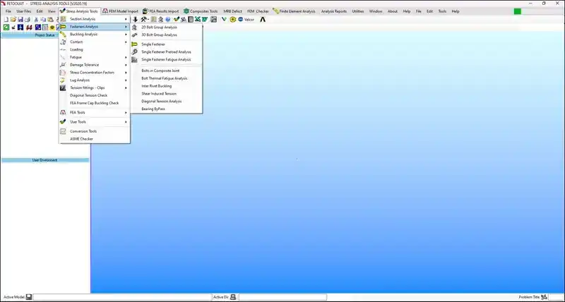
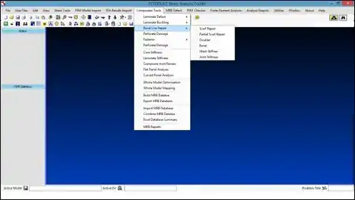
FEToolKit
MRB
Composites
BOEING 787 · GENX ENGINE
787 Dreamliner — ANA Livery
GE ENGINE · THRUST REVERSER COWL
787 GE Nacelle — Trans-Cowl Assembly
FEA · VON MISES STRESS · THRUST REVERSER ASSEMBLY
Thrust Reverser Open-Cowl Von Mises Stress Analysis
Max 1200 MPa · Internal nacelle structure · Linear static FEA · FACC Austria
Bond Line Repair · Laminate Analysis · MRB Database
Thrust Reverser & Trans-Cowl Analysis
Steve completed detailed stress and finite element analysis of the Boeing 787 thrust reverser assembly and trans-cowl for both the GE and Rolls-Royce engine variants, working at the FACC design office in Austria. The thrust reverser structure is a highly loaded composite assembly requiring rigorous FEA for airworthiness certification.
Thrust ReverserTrans-CowlGE & RRFACC Austria
FEToolKit — MRB & Composite Analysis
The development and use of FEToolKit MRB (Material Review Board) and damaged composite structural analysis tools were central to supporting programme expedition in a timely manner. FEToolKit provides specialised composite damage, bond line repair, and laminate defect analysis capabilities tailored to aviation MRB requirements.
FEToolKitMRBComposite DamageBond Line Repair
CFRP Nacelle Structural Substantiation
The 787 nacelle and thrust reverser cowl structure is fabricated from carbon fibre reinforced polymer — one of the most structurally demanding composite applications in commercial aviation. Analysis addressed ply-by-ply laminate assessment, fastener pull-through, delamination risk, and compliance with CS-25 / FAR 25 ultimate load requirements under both thrust and reverser actuation loading.
CFRP NacelleCS-25Ply-by-PlyActuation Loads
Fleet-Wide Method Development · Boeing Commercial Aircraft
The shear flow bypassing each fastener group must be determined from the global load path. Each fastener carries a fraction of the total shear, and the bypass component drives the net section and fitting web stress.
Fitting Bending Stress
The eccentricity between the fastener load line and the fitting attachment lug generates a bending moment, producing prying and bending stresses in the fitting flange — critical for sizing the fitting thickness and radius.
Lug Tension Stress
The net tension area through the lug eye must be checked against ultimate tensile and bearing allowables. Stress concentration factors at the bore and edge distance interact with the applied pin load.
Fleet-Wide Method Development
Steve developed a rigorous method — combining empirical sizing with validated FEA — for the analysis of tension fittings, applied fleet-wide across the Boeing commercial aircraft fleet. With over 200 tension fittings per aircraft, a consistent, efficient methodology is essential to manage the certification workload while ensuring structural integrity at every joint.
Fleet MethodEmpirical Sizing200+ Fittings
FEA Joint Modelling
Three-dimensional solid-element finite element models of the fitting, attached spar or rib, and fastener interfaces are used to determine the stress distribution in the fitting web, flange, and lug. Contact elements at fastener bores capture load transfer and bearing stress concentration, with results validated against classical hand analysis methods.
3D Solid FEAContact ElementsBearing Stress
Structural Sizing & Certification
The method addresses FAR 25 / CS-25 limit and ultimate load requirements, fatigue life, and damage tolerance as required. Output includes fitting geometry sizing recommendations, margin-of-safety summaries, and supporting documentation for DER/DMER certification packages used across multiple aircraft types.
FAR 25 / CS-25Margin of SafetyDER Package
Royal Air Force · Harrier
Harrier Fly-By-Wire Modification
‘Royal Airforce’ Harrier fly by wire modification. Stress analysis of FBW actuators and feel spring unit.
Fly-By-WireStress AnalysisFBW ActuatorsFeel Spring Unit
BAe Jetstream · G-NFLA
Interior Configuration
Steve completed the design and stress analysis of a new interior configuration.
This section is dedicated to the remarkable individuals — colleagues, mentors, clients, and collaborators — whose expertise, vision, and partnership contributed to the projects and programmes represented here. Their names and stories will be added over time.
Jet Propulsion Pioneer · Sir Frank Whittle
Sir Frank Whittle OM KBE (1907–1996) — RAF officer and engineer who invented the turbojet. He patented the concept in 1930 while still a junior officer, and on 12 April 1937 his Power Jets WU became the first turbojet engine to run. The Whittle W.1 went on to power Britain’s first jet aircraft, the Gloster E.28/39, on 15 May 1941 — and his work laid the foundations for every jet engine flying today.
JET PROPULSION
Sir Frank Whittle
RAF officer & engineer — inventor of the turbojet
POWER JETS
Whittle with an Early Turbojet
The engine concept that launched the jet age
Boeing Everett · Production Line
BOEING EVERETT · PRODUCTION LINE
Steve with William Mulkey Jnr
Boeing 747 production line, Everett, Washington
🔒
Awaiting approval to publish
Click to enter passcode
747-8 PRODUCTION LINE · BULKHEAD 2598
Steve · 747-8 Production Line — Bulkhead 2598, Boeing Everett
Inside the 747-8 airframe, Boeing Everett, Washington
Left: Steve with William Mulkey Jnr on the Boeing 747 production line at Everett, Washington. Right: Steve on the 747-8 production line, inside the airframe at bulkhead 2598, Boeing Everett. Boeing was a place of employment for Steve for many years — Everett is one of the world's largest manufacturing facilities.
BOEING EVERETT
Gary at Everett, FEB 2010 First Flight
🔒
Awaiting approval to publish
Click to enter passcode
BOEING EVERETT · DREAMLIFTER
Steve at Everett, FEB 2010 First Flight
Boeing Everett — The Team
BOEING EVERETT · FULL DESIGN & ANALYSIS TEAM
Boeing 747-8 Design & Analysis Team — Everett, Washington
The extraordinary team behind one of the world's most complex aircraft programmes
🔒
Awaiting approval to publish
Click to enter passcode
BOEING 787 · SECTION 48 TEAM
787 Section 48 Team — 2006
🔒
Awaiting approval to publish
Click to enter passcode
Boeing & International Teams
BOEING · BLENDED SPLIT WINGLET · FUTURE DEVELOPMENT
Boeing Engineering Team — Lobby Group Portrait
Assembled beneath the Blended Split Winglet display sculpture
BOEING · FACTORY FLOOR
On the Production Line
Engineers with primed fuselage section behind
🔒
Awaiting approval to publish
Click to enter passcode
SHANGHAI · PUDONG
International Program Team
Pudong skyline · Shanghai Tower under construction
C919 Spoiler Critical Design Review · International Engineering Team
CDR Team Photos · COMAC, China
LEADERSHIP TEAM · CDR DAY
C919 Spoiler Program — Engineering Leadership
Standing before the bilingual CDR banner on review day in China
REVIEW IN SESSION
Structural Analysis Presentation
CDR session in progress · COMAC conference room
JOINT INTERNATIONAL ENGINEERING TEAM
C919 Spoiler CDR — Full Engineering Team
COMAC and international partner engineers · Bilingual programme banner visible behind
CROSS-BORDER COLLABORATIONCDR PASSED
COMAC C919 · International Engineering Programme · 2010 onwards
The COMAC C919 narrow-body programme drew engineers and programme managers from across China, Europe and North America. The portraits below capture some of the colleagues Steve worked with on structural-analysis methodology, sizing, and certification-basis questions — in conference rooms in Shanghai, beer halls in Munich, and on the long flights and longer working sessions in between.
SHANGHAI · COMAC C919 PROGRAMME
Steve & Michael Niu (centre-right)
Memorable Person
Michael C. Y. Niu
Author · Airframe Stress Analysis and Sizing · Conmilit Press
Steve and Michael Niu in Shanghai during the COMAC C919 development phase. Michael C. Y. Niu — formerly a senior structural engineer at Lockheed and Boeing — is the author of the standard reference texts Airframe Stress Analysis and Sizing and Airframe Structural Design, used worldwide as the practical handbooks of commercial aircraft structural engineering.
During the C919 development programme, Steve worked alongside Michael and the COMAC engineering team on structural-analysis methodology, sizing approach and certification-basis questions — drawing directly on the methods Michael had codified in his books over a four-decade career in commercial aircraft stress engineering.
Steve and William in Shanghai during the COMAC C919 development phase. An evening together with colleagues over dinner — the everyday side of an international engineering programme, where working relationships across continents are built in the spaces between formal review meetings.
COMAC C919ShanghaiInternational Team
MUNICH · COMAC C919 PROGRAMME
Steve & Dr Shiu (C919 Design Manager)
KARAOKE · SHANGHAI
Karaoke Shanghai prior to final C919 Critical Design Review
Note to all budding karaoke folks: the words come out rolling from right to left!
Memorable Person
Dr Shiu
COMAC C919 Design Manager · Munich, Germany
Steve with the C919 design manager, Dr Shiu, in Munich, Germany during the COMAC C919 development phase. The C919 was a truly international programme — design reviews and supplier coordination took the team across China, Europe, and the United States. Moments like this one in a Munich beer hall capture the human side of those long campaigns: the friendships built across cultures and time zones that made the technical work possible.
Steve has spent a substantial part of his career on aero-engine structures and systems — working at Rolls-Royce in the UK, Rolls-Royce Deutschland at Dahlewitz, and on the Eurojet EJ200 / Pierburg fuel system for the Eurofighter Typhoon. His work spans three-shaft civil turbofans, regional-jet engines, military afterburning powerplants, whole-engine models and fuel-system hardware.
On the aero-engine programmes, Steve's role spanned design support, detailed stress analysis, development & qualification testing, and certification / permits to fly.
Rolls-Royce · United Kingdom · Aero Engines
ROLLS-ROYCE — TRENT 500 & BR715 ENGINE ANALYSIS
HP Turbine & Fan Blade Stress · Blade-Off · Spin-Pit Prediction · Probabilistic Life
Three-Shaft Architecture — Fan · IP · HP · Combustor · Turbine Stages
A340-500 / -600 powerplant · ~56,000 lbf class · derived from the Trent 700/800 family
A340-500/60056,000 LBF CLASS
Steve's Contribution
At Rolls-Royce in the United Kingdom, Steve worked across two of the company's three-shaft turbofan programmes, delivering detailed structural analysis of the highest-load components in the engine — the rotating blades and discs that operate at the limits of what materials science allows.
On the Trent 500, Steve completed the detailed empirical and finite element analysis of the high-pressure turbine blades and the fan blade. The work covered steady centrifugal and aerodynamic loading, thermal gradients across the blade airfoil and root, high-cycle and low-cycle fatigue, creep at sustained operating temperatures, and resonance avoidance through Campbell-diagram and forced-response analysis. He also led the blade-off analysis — the certification case that demonstrates the engine and its containment can withstand the release of a complete fan blade at maximum RPM — together with the fatigue and fracture damage-tolerance analysis of the blade root, the most heavily-loaded geometric feature in the engine.
On the BR715 (the BMW Rolls-Royce regional-jet engine for the Boeing 717), Steve completed detailed stress analysis of the turbine, spin-pit test prediction analysis for rotating components, and probabilistic life analysis of blades and discs — using statistical methods to predict cyclic life with quantified confidence bounds, supporting fleet-wide maintenance and retirement intervals.
Fan blade detailed analysis plus full blade-off certification case — release at maximum RPM and downstream load path.
Blade Root F & DT
FIR-TREE
Fatigue and fracture damage-tolerance at the blade-root fir-tree interface — the most highly-stressed geometric feature in the engine.
BR715 · Probabilistic
SPIN-PIT & PLA
Turbine stress, spin-pit test prediction and probabilistic life analysis of blades and discs — statistical cyclic life with confidence bounds.
A Note on Heritage
“We are fortunate to stand on the shoulders of giants.”
Every modern Rolls-Royce engine — every Trent, every BR-series, every UltraFan — owes its existence to a century of British engineering heritage. The Merlin that won the Battle of Britain, the Derwent and Nene that opened the jet age, the Conway and RB.211 that defined the three-shaft turbofan — each was the work of extraordinary engineers in Derby, Barnoldswick and beyond. To analyse a Trent 500 turbine blade or a BR715 disc is to inherit that legacy.
ROLLS-ROYCE MERLIN · DERBY · 1944
R.M. 14S.M. Mk 100 V-12
The engine that won the Battle of Britain
NIGHTINGALE ROAD · DERBY · 1912
The Marble Hall · Rolls-Royce Limited
Birthplace of the Merlin · Grade II Listed
SIR HENRY ROYCE · DERBY HQ
Statue by Francis Derwent Wood
Co-founder · The engineer behind the marque
BATTLE OF BRITAIN MEMORIAL WINDOW · 1949
Hugh Easton · Marble Hall, Derby
Figure atop a Merlin propeller, eagle behind · Unveiled by Lord Tedder
SIR FRANK WHITTLE OM KBE CB FRS FRAeS
Inventor of the Turbojet Engine
The W.1 first ran in 1937 and powered the Gloster E.28/39 — Britain's first jet aircraft — in May 1941. The foundation of the modern jet age.
Rolls-Royce Deutschland · Dahlewitz · Centre of Excellence · Business Aviation
ROLLS-ROYCE BR710 & BR715 — WHOLE-ENGINE FEM & STATOR ANALYSIS
Whole-Engine FE Model · Stator Detailed Stress · Vibration · JSF Software Bridge
WEM
Whole-Engine FE
STATOR
Detailed Stress
MODAL
Vibration · Fixed Comps
JSF
SC03 → ANSYS / DARWIN
ROLLS-ROYCE DEUTSCHLAND · DAHLEWITZ · BRANDENBURG
Centre of Excellence for Business Aviation Engines
South of Berlin · two-shaft engine design, manufacture & test · ~2,500 staff from 60 nations
BR710BR715BR725 / PEARL
ROLLS-ROYCE BR710 · CUTAWAY
Two-Shaft Architecture · 48-inch Fan
10-stage HP compressor · 2-stage HP & LP turbines
BR710 ON STAND · TEMPELHOF
Forced-Mixer Exhaust · Instrumented Test Build
Chevron exhaust mixer · LP turbine casing with wiring harnesses
Steve's Contribution
At Rolls-Royce Deutschland in Dahlewitz, Germany — the company's centre of excellence for business aviation engines — Steve worked across the BR700 family on the highest-level structural simulation tasks: whole-engine modelling, detailed stator analysis, and the software infrastructure that connects different finite-element worlds together.
Steve completed the finite element analysis of the Whole-Engine Model (WEM) for the BR710 and BR715 — the integrated FE representation of the complete engine assembly used to predict overall casing deflections, rotor-to-stator clearance closures under flight loads, manoeuvre and gyroscopic effects, and the engine's contribution to airframe loads. He also delivered the detailed stress analysis of the main stator and the vibration analysis of fixed components, including modal extraction, forced-response analysis and identification of resonance avoidance margins across the operating envelope.
In parallel, Steve developed a software program to translate SC03 finite element analysis models and results into ANSYS and DARWIN, supporting the Joint Strike Fighter (JSF / F-35) project. SC03 is the Rolls-Royce in-house finite element solver historically used across UK and German programmes; ANSYS is a leading commercial FE package and DARWIN is the probabilistic damage-tolerance code maintained by the Southwest Research Institute. The translator allowed BR-series engine models built in SC03 to be re-used directly in JSF-relevant probabilistic life and damage-tolerance assessments without manual re-meshing — a significant productivity win across the programme.
Whole-Engine FE Model
WEM
Integrated FE model of the complete BR710 / BR715 assembly — casing deflection, rotor-to-stator clearance closure, manoeuvre and gyroscopic loads, airframe interface.
Main Stator Stress
DETAILED FE
Detailed stress analysis of the main stator load path — vane platforms, attachment lugs, casing flanges and bolted joints under thermal and mechanical loading.
Fixed Component Vibration
MODAL
Modal extraction, forced response and resonance-avoidance margins for fixed structures across the operating envelope — Campbell-diagram clearance.
JSF · FE Translator
SC03 → ANSYS / DARWIN
Custom software bridge translating Rolls-Royce SC03 FE models and result fields into ANSYS and DARWIN — enabling re-use in JSF probabilistic damage-tolerance work.
Cast housing carrying the HP gear pump, LP centrifugal pump and FMU
Steve's Contribution · Subject Matter Expert
Across four years spanning preliminary design through final production design, Steve was the structural-analysis lead on the EJ200 fuel system — first at Lucas Aerospace during the initial design phase, and then on-site at Pierburg in Neuss, Germany during development and qualification testing.
Steve completed the detailed stress analysis — using empirical methods and ANSYS finite element analysis — of the engine's fuel-system pressure-carrying components: the main fuel metering unit, the centrifugal fuel pump, and the main fuel gear pump. The analyses covered burst, proof, fatigue and damage-tolerance loadings under the full EJ200 operating envelope — including reheat-on transients, negative-g and inverted-flight conditions, and the temperature extremes of supersonic combat operations.
Steve was the Subject Matter Expert and Technical Representative on the Eurofighter Development Committee, presenting analyses, design-change rationale and qualification evidence to the multi-national engineering authority for the programme.
“It was an exciting time working on the bigger project — Eurofighter.”
RHEINMETALL · NEUSS
Riverside Facility
North Rhine-Westphalia, Germany
PIERBURG GMBH · WERK NIEDERRHEIN
Visitor & Office Entrance
Where Steve supported development & qualification testing
PIERBURG · NEUSS
Steve in his office at Pierburg, Neuss
During Eurofighter & EJ200 development
Main Fuel Metering Unit
FMU STRESS
Detailed stress analysis of the EJ200 main fuel metering unit — pressure casing, valve bores, manifold flanges and electro-hydraulic interface ports.
Centrifugal Fuel Pump
PUMP CASING
Empirical and FE stress analysis of the centrifugal LP fuel pump casing, impeller mounting interface and shaft housing under full reheat fuel flow.
Main Fuel Gear Pump
GEAR PUMP
Stress analysis of the main HP gear-pump housing, gear-cavity walls and bearing pockets — pressure-pulsation, ovalisation and tooth-engagement loads.
Development Committee
SME · TECH REP
Subject Matter Expert and Technical Representative on the Eurofighter Development Committee — design changes, qualification evidence, multi-national engineering authority.
General Electric · Cincinnati, Ohio
GE CF34 Fan & Blade Analysis
Fan Blade · Blade-Root Fixing · Regional-Jet Turbofan
CF34
GE Turbofan
FEA
Blade Root
GENERAL ELECTRIC · CF34
CF34 Regional-Jet Turbofan
The high-bypass turbofan family powering regional and business jets
FEA · BLADE-ROOT FIXING ANALYSIS
Blade-Root Fixing — Peak Stress Contour
2D finite element total peak stress at the blade-root fixing
At General Electric in Cincinnati, Ohio, Steve carried out the detailed stress analysis of the CF34 fan and fan blades — including the critical blade-root fixing, where centrifugal loads are transferred from the blade into the disc through the dovetail. The finite element work resolved the peak stresses at the root fillet radii that govern blade life.
The analysis addressed steady centrifugal loading, the stress concentrations at the fixing contact faces and fillets, and the margins required for a long-life, high-cycle fan component in a regional-jet turbofan.
On the CF34 fan, Steve's role was detailed stress analysis of the fan, blades and blade-root fixing.
GE CINCINNATI · THE TEAM
CF34 Engineering Team
The engineers behind the CF34 fan analysis, General Electric, Cincinnati
Memorable Team
Steve looks back on the CF34 programme at GE Cincinnati with great fondness — a talented, collaborative team working at the leading edge of commercial turbofan technology. The fan and blade-root analysis demanded close teamwork between stress, design and the wider engineering group.
Steve served as Chief Stress Engineer at Airship Industries (UK) Ltd, holding design approval authority on the iconic Skyship 600 programme. His structural engineering work underpins some of the most recognisable airships ever built — including vehicles operated by the US Navy, deployed for James Bond film production, and used in commercial surveillance and advertising roles worldwide.
On the airship programmes, Steve's role spanned design support, detailed stress analysis, development & qualification testing, and certification / permits to fly — including his CAA-approved signatory authority for airworthiness.
Type Record
Original cover
Skyship 600 — Type Record
The Skyship 600 Type Record (Serial No. 002) shown here bears Steve's signature as Chief Stress Engineer, dated 16 March 1987. Design Approval No. SK/8722/81. This document represents the definitive structural engineering authority record for one of the world's most advanced non-rigid airship programmes of its era.
Chief Stress EngineerType Record AuthorityCAA Design Approval
AIRSHIP INDUSTRIES
Skyship 600 G-BIHN
GONDOLA DETAIL
Skyship 600 — Gondola & Vectored Thrust
FEA · VON-MISES STRESS
Gondola Aerodynamic Load Analysis
Max 94.6 MPa · Safety factor 2.64 · 185,432 elements
FEA · ENVELOPE & TAIL · VON-MISES STRESS
Airship Envelope & Tail Von-Mises Stress Analysis
Envelope max 118 MPa · Vertical fin max 115 MPa · q = 600 Pa · G-BIHN
CFD · AERODYNAMIC FLOW & PRESSURE ANALYSIS
Airship Aerodynamic Flow & Pressure — Envelope
Velocity 22.2 m/s · q = 600 Pa · Re = 1.5×10⁸ · G-BIHN
✅
Official Authority
British CAA Approved Signatory for Airworthiness — Flight Vehicle for Test Flight and Commercial Use
Steve held official approval from the UK Civil Aviation Authority as an authorised signatory, enabling him to certify lighter-than-air flight vehicles for both experimental test flight operations and commercial service — a distinction held by very few engineers in the UK airship industry.
American Institute of Aeronautics and Astronautics — AIAA
Steve was an active member of the Lighter-Than-Air Section and served on the LTA Technical Committee, where he supported research and development into structural analysis methods for airship envelopes. His work addressed the complex, non-linear behaviour of pressure-dependent envelope shape and stiffness.
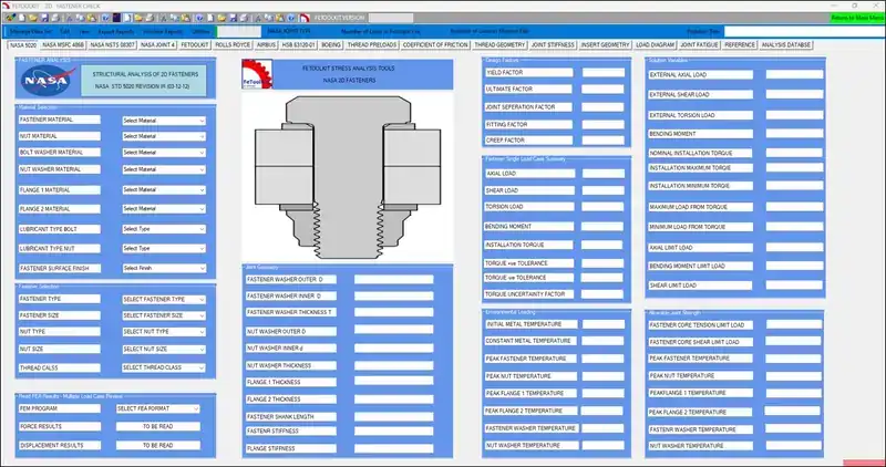
During this period, Steve was Chief Engineer at Airship Industries. He was responsible for preparing the supporting technical documentation required to certify the first airship under the British Civil Airworthiness Authority's Section Q requirements for commercial and passenger transport. Steve also developed FETOOLKIT, a structural analysis tool designed to process aerodynamic loads and acceleration data for use in full-scale finite element analysis of the airship envelope and gondola.
As Chief Stress Engineer, Steve was responsible for all primary and secondary structural analysis of the Skyship 600 envelope, gondola, fin structures, and mooring systems.
Envelope StressGondola Structure
Defence & Surveillance Variants
Structural modifications for US Navy surveillance gondola integration including sensor payload attachment hardpoints, antenna arrays, and modified gondola structures for extended mission endurance.
US NavyISR Systems
Special Operations & Film
The Skyship was used in James Bond film A View to a Kill (1985) as the "Zorin Industries" airship. Steve provided structural clearance for this iconic production use.
A View to a Kill1985
The Skyship 600 Legacy
The Skyship 600 remains one of the most technically advanced non-rigid airships ever certified, holding a full CAA Type Certificate. Under Dr. Clamp's structural authority, the programme delivered vehicles that served commercial, film, and military roles across three continents.
Classical thin-shell theory applied to the axisymmetric balloon envelope. Principal stresses σ₁ (meridional) and σ₂ (hoop) derived from Laplace’s equation for a pressurised membrane. Von Mises criterion combines these to give equivalent stress for failure assessment against the coated fabric ultimate tensile strength.
Thin-shell theoryBiaxial stressLaplace equation
Load Tape & Seam Loads
Meridional load tapes carry the primary tensile load from buoyancy lift, running pole-to-pole and concentrating stress at attachment nodes. Seam loads between adjacent gores were calculated for each panel width configuration, including peel and shear components at bonded/stitched seam lines. Joint efficiency factors applied per material test data.
Pressurised gondola shell assessed for hoop and axial stresses under internal pressure differential at altitude. Viewport/port cutouts analysed for stress concentration factors (K_t). Interface loads between gondola frame and suspension cable attachment points sized for worst-case dynamic landing and emergency descent load cases.
Pressure vesselStress concentrationLanding loads
Suspension Cable System
Cable tensions resolved from buoyancy force, gondola mass, ballast, and equipment loads. Load distribution between n cables analysed for unequal loading in asymmetric flight attitudes. Cable-to-envelope attachment fittings designed with stress concentration mitigation and fatigue life calculation for repeated inflation/deflation cycles.
Cable tension analysisFitting designFatigue life
Airship Industries · Cardington · 1987
Memorable People
The extraordinary people behind the Skyship programme at Airship Industries — the visionaries, engineers, and designers who made the world's most advanced non-rigid airship a reality at Cardington, Bedfordshire.
Design Team · Cardington · February 1987
Roger Munk
Founder and driving force of Airship Industries Ltd. Roger Munk was one of the most visionary figures in lighter-than-air aviation — his passion and technical insight underpinned the entire Skyship programme and inspired a generation of airship engineers.
Reg Hilsden
Senior member of the Airship Industries design team at Cardington. Reg's engineering expertise and deep knowledge of lighter-than-air structures contributed directly to the structural integrity and design authority of the Skyship 600 programme.
Steve & Design Team
Steve, serving as Chief Stress Engineer, and the wider Airship Industries design team at Cardington — the talented group of engineers who certified the Skyship 600 to CAA standards. Together they produced one of the most structurally advanced non-rigid airships ever built.
Cardington in Bedfordshire was the historic home of British airship development — the vast green sheds that housed the R100 and R101 in the 1920s and 1930s became the base for Airship Industries in the 1980s. Working in these extraordinary surroundings, surrounded by the history of lighter-than-air flight, the design team at Airship Industries created a new chapter in British aviation history with the Skyship 600.
LIGHTER-THAN-AIR
Airship Pioneer · R-100 Era
Significant Locations in Steve's Airship Career
Memorable Places
Beyond the people, certain places have shaped Steve's work in lighter-than-air systems — historic airfields and engineering hangars where the heritage of the discipline is still tangible.
Memorable Place · Lakehurst, New Jersey
NAS Lakehurst · U.S. Navy Airship Heritage
U.S. NAVY ZPG-3W
Goodyear ZPG-3W Airborne Early-Warning Airship
NAS Lakehurst, New Jersey · gondola preserved on site during Steve's visit
PIASECKI HELI-STAT
Hybrid Airship + Four Helicopters
Airship envelope on tubular support carrying four H-34 rotorcraft · moored at Lakehurst
At Lakehurst, New Jersey, Steve spent time supporting the Sentinel 5000 programme at the request of his peers. His brief was to “learn as much as possible from the ZPG-3W about U.S. Navy airship operations”, with the ZPG-3W gondola still housed in the hangars. For an aerospace engineer, Lakehurst was a particularly memorable and significant place to work.
While there, Steve also saw the Piasecki Heli-Stat moored on site — an unusual hybrid vehicle that combined an airship with four helicopters attached by a tubular support structure.
NAS LakehurstU.S. NavySentinel 5000ZPG-3WPiasecki Heli-StatHybrid LTA
CARDINGTON
Airship Industries at the Cardington Sheds
SKYSHIP 600 · G-SKSC
Walk-out from the Hangar
Section 01C — Lighter-Than-Air · Balloon Systems
BALLOONS
Solar · High-Altitude · Scientific · Record-Breaking
A Personal Tribute
“What a privilege it was in the 1980s to complete the stress analysis on your brilliant designs. RIP Julian”
— Steve
Julian Nott
Balloon Pioneer
Steve provided design support, detailed stress analysis, development & qualification testing and certification / permits-to-fly support on pioneering balloon designs by the legendary Julian Nott — one of the greatest balloon pilots and designers in history, holder of multiple world altitude records and pioneer of the solar balloon.
1980sBalloon Program Era
SolarBalloon Specialist
High AltitudeScientific Platforms
World RecordsProgram Supported
Program Gallery
SOLAR BALLOON
G-BAVU — Julian Nott Solar Balloon
RECORD ATTEMPT
Julian Nott with the Explorer balloon
GONDOLA DESIGN
Julian Nott ICI Innovation Gondola — Museum Display
HIGH ALTITUDE
NASA Super Pressure Balloon launch
Structural Stress Analysis of Gondola, Envelope & Support Cables
Steve was responsible for the complete structural stress analysis of Julian Nott balloon systems — covering the pressurised envelope membrane, load tapes, equatorial reinforcement band, gondola pressure vessel, and suspension cable system. Analysis completed to UK CAA airworthiness standards.
Envelope Membrane Analysis
Classical thin-shell theory applied to the axisymmetric balloon envelope. Principal stresses σ₁ (meridional) and σ₂ (hoop) derived from Laplace's equation. Von Mises criterion combines these to give equivalent stress for failure assessment.
Thin-shell theoryBiaxial stress
Gondola Structure
Pressurised gondola shell assessed for hoop and axial stresses under internal pressure differential at altitude. Viewport cutouts analysed for stress concentration factors. Interface loads between gondola and suspension cables sized for worst-case dynamic loads.
Pressure vesselStress concentration
IN MEMORY OF JULIAN NOTT
Julian Nott set over 90 world ballooning records across a career spanning five decades. His innovative designs — including the solar balloon and advanced pressurised gondolas — pushed the boundaries of lighter-than-air aviation. Steve had the honour of performing structural stress analysis on several of Julian's pioneering designs during the 1980s, contributing quietly but critically to some of ballooning's greatest achievements. Julian Nott's gondola is now on permanent museum display — a fitting tribute to a man who turned engineering imagination into sky-high reality.
Memorable People
People Who Shaped This Work
This section is dedicated to the remarkable individuals — colleagues, mentors, clients, and collaborators — whose expertise, vision, and partnership contributed to the projects and programmes represented here. Their names and stories will be added over time.
Content coming soon. Contact info@steveclamp.com to contribute a memory or nomination.
Section 02
ROCKETS
Propulsion · Launch Vehicles · Trajectory
From expendable launch vehicles to next-generation reusable rocket systems, Steve's expertise in propulsion engineering and trajectory design has contributed to both government space programmes and the commercial launch revolution.
22+Launch Projects
8Vehicle Types
3ESA Contracts
LEO/GTOOrbits Served
Propulsion Systems
Liquid bipropellant, solid, and hybrid rocket engine analysis. Combustion stability modelling, nozzle design, and thrust vector control (TVC) system integration.
LOX/RP-1HTPB SolidTVC Systems
Structural Loads & TPS
Ascent load analysis, aeroelastic assessment, and thermal protection system (TPS) design for re-entry vehicles. Ablative and actively-cooled TPS selection and sizing.
Booster recovery system design, landing leg dynamics, engine reuse qualification, and refurbishment cycle analysis supporting the new era of cost-effective launch.
Recovery SystemsRefurbishmentCost Modelling
Launch Program Contributions
Steve has contributed to small satellite launcher development programmes across Europe and performed independent technical authority reviews for ESA-funded launch vehicle studies. His trajectory optimisation work on micro-launcher designs achieved a 15% mass-to-orbit improvement over baseline configurations.
ARTEMIS II · SLS · NASA
SPACE LAUNCH SYSTEM
Heavy-Lift Architecture · Orion Crew Vehicle
Featured Program · SLS
Valves, Manifolds & Cryogenic Fuel Control Systems
Over a span of more than ten years, Steve completed the detailed thermal, dynamic, static, fatigue and fracture analyses on 30+ valves, manifolds and oxygen/hydrogen fuel-control systems for NASA's Space Launch System — the heavy-lift vehicle powering the Artemis programme back to the Moon.
Cryogenic LOX/LH₂ propellant feed hardware operates at the extreme intersection of thermal shock, pressure cycling and structural fatigue. Each component required full lifecycle qualification — from boost-phase dynamic loads to long-duration creep and fracture-mechanics review against NASA-STD-5009 and -5019 acceptance criteria.
Whilst working at The Spaceship Company on the SpaceShipTwo programme, Steve held two successive lead-stress engineering roles on the suborbital vehicle’s primary airframe.
ROLE · 01
Lead Stress Engineer Feather System & Support Structure
Primary structural responsibility for SpaceShipTwo’s signature pneumatically-actuated feather re-entry system — the wing-pivot mechanism that enables shuttlecock-stable, hands-off atmospheric re-entry from the edge of space.
ROLE · 02
Lead Stress Engineer Wing Spars & Ribs
Lead-stress engineering authority for the composite wing primary structure — spars and ribs carrying ascent boost loads, supersonic flight loads, and the asymmetric feather-deployed re-entry attitude.
ACTUAL CERTIFICATES FLOWN INTO SPACE, AWARDED BY THE COMPANY EXECUTIVES TO STEVE FOR HIS WORK TO SUPPORT FIRST POWERED ROCKET FLIGHT AND FIRST FLIGHT INTO ORBIT AND SAFE RETURN OF ALL CREW AND PASSENGERS.
Please see the CREDENTIALS section to view these certificates.
New Shepard · Propulsion Systems
BLUE ORIGIN
Steve completed stress analysis on fuel valves, manifold and quick disconnect systems.
DESIGN CDR · CAPE CANAVERAL
Taken during Design CDR — Cape Canaveral, Florida
DESIGN CDR · NEW SHEPARD CREW CAPSULE
Taken during Design CDR — Blue Origin New Shepard rocket booster
Note the seven turtles on the New Shepard crew capsule (1 turtle = 1 mission)
Projects
ULA VULCAN CENTAUR
Vulcan Engine System Stress Analysis
Memorable People
People Who Shaped This Work
This section is dedicated to the remarkable individuals — colleagues, mentors, clients, and collaborators — whose expertise, vision, and partnership contributed to the projects and programmes represented here. Their names and stories will be added over time.
Among the pioneers whose vision shaped rocketry and the private spaceflight era:
PHOTO GODDARD
FATHER OF MODERN ROCKETRY
Robert H. Goddard
1882–1945 · USA
Built and flew the world's first liquid-fuelled rocket in 1926. His 214 patents — including multi-stage design and gyroscopic guidance — laid the engineering foundations of the Space Age.
PHOTO VON BRAUN
ARCHITECT OF THE SATURN V
Wernher von Braun
1912–1977 · Germany / USA
Lead designer of the Saturn V launch vehicle that carried Apollo to the Moon. First director of NASA's Marshall Space Flight Center and a defining figure in human spaceflight.
PHOTO RUTAN
SCALED COMPOSITES · DESIGNER
Burt Rutan
b. 1943 · USA
Designer of SpaceShipOne, the first privately-built crewed craft to reach space. Founder of Scaled Composites and a radical innovator in lightweight composite airframes.
PHOTO ALLEN
FINANCIER · SPACESHIPONE
Paul Allen
1953–2018 · USA
Microsoft co-founder who funded the SpaceShipOne programme that won the Ansari X Prize in 2004. Later backed Stratolaunch, advancing private access to space.
PHOTO BRANSON
VIRGIN GALACTIC · FOUNDER
Sir Richard Branson
b. 1950 · United Kingdom
Founder of Virgin Galactic, commercialising the SpaceShipOne design into SpaceShipTwo. Flew to the edge of space aboard VSS Unity in July 2021, opening the suborbital tourism era.
PHOTO ANSARI X PRIZE
$10M COMPETITION · 2004
Ansari X Prize
Won 4 October 2004 · Mojave
The $10M prize that launched the private spaceflight industry — awarded to SpaceShipOne for two crewed flights to 100 km within two weeks. Catalyst for Virgin Galactic and the New Space era.
🔒Restricted — passcode requiredPermission has not been received to publish this image
THE SPACESHIP COMPANY · ALL-HANDS
The Spaceship Company — Full Company Assembly
The extraordinary team behind Virgin Galactic's SpaceShipTwo programme
Permission has not been received to publish this image.
🔒Restricted — passcode requiredPermission has not been received to publish this image
FEBRUARY 23RD, 2018
The Spaceship Company · All-Hands Event
Permission has not been received to publish this image.
🔒Restricted — passcode requiredPermission has not been received to publish this image
SPACE SHUTTLE ENDEAVOUR · GALA
Celebration Under the Endeavour
Permission has not been received to publish this image.
🔒Restricted — passcode requiredPermission has not been received to publish this image
CALIFORNIA SCIENCE CENTER
Space Shuttle Endeavour — Event View
Permission has not been received to publish this image.
🔒Restricted — passcode requiredPermission has not been received to publish this image
BLUE ORIGIN · BLUE MOON LANDER
Blue Moon Lunar Lander — Program Team
Team assembled in front of the Blue Moon lunar lander mock-up
Permission has not been received to publish this image.
🔒Restricted — passcode requiredSteve with TSC colleague
THE SPACESHIP COMPANY
Steve with TSC colleague
In Memoriam
Michael T. Alsbury — "SCAT 23"
Scaled Composites Test Pilot, lost during the powered flight test (PF04) of SpaceShipTwo, N339SS, near Mojave, California, on October 31, 2014.
"Ad Astra per Aspera" — Through hardships to the stars.
Michael Alsbury was a brave and skilled test pilot who gave his life in the pursuit of opening space to humanity. He and all those who worked on the SpaceShipTwo programme are remembered with deep respect and gratitude by everyone who shared in that extraordinary mission.
Scaled CompositesSpaceShipTwoOctober 31, 2014Ad Astra per Aspera
Section 03
SATELLITE
Orbital · Payload · Ground Segment
Satellite engineering demands precision at every scale. Steve's work spans LEO constellations for Earth observation, GEO telecommunications platforms, and cubesat technology development for research institutions.
On the space programmes, Steve's role spanned design support and detailed stress analysis.
Fokker · Schiphol Airport Amsterdam · Large Satellite Program
L-SAT SATELLITE — SOLAR MAST DEPLOYMENT
Steve completed the static and dynamic stress analysis of the L-SAT satellite solar mast during explosive deployment, using NASTRAN finite element analysis and empirical stress analysis methods, at the Fokker design office, Schiphol Airport, Amsterdam.
NASTRAN
FEA Solver
L-SAT
Large Satellite
Dynamic
Deployment
Fokker
Amsterdam
L-SAT · SOLAR MAST · EXPLOSIVE DEPLOYMENT ANALYSIS
Large Satellite Solar Mast — Explosive Deployment Dynamic Analysis
The L-SAT solar mast deployment is initiated by a pyrotechnic (explosive) release mechanism — the sudden energy release imparts high-rate dynamic loads into the mast structure during unfurling. Steve performed both the static load analysis and the dynamic transient response of the mast under these impulsive deployment loads, capturing the shock and vibration environment.
Pyrotechnic ReleaseTransient DynamicShock Loads
NASTRAN FEA — Static & Dynamic
MSC NASTRAN was used to build the finite element model of the solar mast, including beam, shell, and joint elements representing the mast boom, hinges, and solar panel array. Static analysis addressed inertia and thermal loads in orbit; dynamic analysis captured the transient response during deployment to identify peak stresses in the mast structure.
MSC NASTRANStatic & DynamicSolar Array FEA
Empirical Methods & Fokker
Empirical stress analysis methods — based on beam theory, energy methods, and established spacecraft structural analysis practice — were applied alongside the NASTRAN results to cross-validate the peak stress and moment predictions. This work was completed at Fokker's design office at Schiphol Airport, Amsterdam, supporting the L-SAT large satellite programme.
3-D Shell-Element FE Code · Thermal · Static · Dynamic · Mirror Concentrators & Support Canisters
SAX
X-Ray Astronomy
3-D SHELL
FE Code Developed
T · S · D
Thermal · Static · Dynamic
ASI · NIVR
Italian-Dutch Mission
BeppoSAX · IN ORBIT · ARTIST IMPRESSION
X-Ray Astronomy Satellite (1996–2002)
Italian Space Agency (ASI) + Netherlands Agency for Aerospace Programmes (NIVR)
BeppoSAX · SPACECRAFT RENDER
Bus & Solar-Array Configuration
Gold thermal blankets · NFI apertures · WFC orthogonal mount
Steve's Contribution · LABEN S.p.A · Milan
At LABEN S.p.A in Milan, Italy, Steve developed and produced the stress-analysis methods for the detailed thermal and structural analysis of the BeppoSAX satellite's X-ray concentrator mirrors — the precision-figured grazing-incidence optics that focused soft X-rays onto the on-board detectors.
To address the analysis problem, Steve developed a bespoke finite element program built around 3-dimensional shell elements capable of simulating the coupled thermal, static and dynamic structural behaviour of the concentrator mirrors and their support canisters. Thin-shell formulations are particularly well-suited to grazing-incidence X-ray mirrors, where shell thickness is a small fraction of the structure's overall radius and where capturing through-thickness thermal gradients and out-of-plane bending is essential to predicting figure error under operational conditions.
The analysis suite supported sizing and qualification of the optics against the full ground-handling, launch and on-orbit thermal-cycling environment — predicting mirror figure distortion, modal response and stress margins. BeppoSAX launched on 30 April 1996 and went on to make one of the landmark astrophysical discoveries of the decade: the first identification of gamma-ray bursts as extra-galactic events, work for which the mission was awarded the Bruno Rossi Prize (1998), the Descartes Prize (2002), the Fermi Prize (2010) and the Shaw Prize (2011).
3-D Shell-Element FE Code
BESPOKE FE
Custom finite element program developed in-house — 3-D shell elements for grazing-incidence optics, coupled thermal/static/dynamic capability.
Concentrator Mirrors
SPACE SCAN
Thermal-gradient and orbital-thermal-cycle distortion prediction for the X-ray concentrator mirror shells; figure-error margins to scientific requirement.
Support Canisters
QUAL ENV
Mirror support canister stress, modal and dynamic response across ground handling, launch loads and on-orbit thermal environment.
Project work covering the thermal, static, dynamic and fatigue analysis of a cryogenic finger assembly for Lucas Aerospace in Birmingham.
Thermal
Analysis
Static
Loads
Dynamic
Response
Fatigue
Life
Cryogenic Finger · COMPONENT RENDER
Thermal / Static / Dynamic / Fatigue Assessment
Project Summary · Lucas Aerospace · Birmingham
Steve carried out the thermal, static, dynamic and fatigue analysis of a cryogenic finger assembly for Lucas Aerospace, Birmingham.
The work focused on structural integrity and thermal behaviour of the assembly under operational loading conditions, combining analytical assessment of temperature effects, static loading response, dynamic behaviour and fatigue durability.
This project is presented within the SATELLITE section as part of Steve's wider experience in precision aerospace and space-related hardware analysis.
Spacelab · ESA / NASA · Marshall of Cambridge Aerospace · UK
Pressurised cylinder housing subsystems for pallet-only missions
SPACELAB · MODULAR ARCHITECTURE
Tunnel · Core · Experiment Module · Pallets
Reconfigurable to each mission's research needs
Steve's Contribution · Marshall of Cambridge Aerospace · UK
At Marshall of Cambridge Aerospace in the United Kingdom, Steve worked on the structural analysis of Spacelab — the European Space Agency's reusable microgravity laboratory that flew aboard the Space Shuttle on 32 missions between 1983 and 1998, supporting research across space plasma physics, solar physics, atmospheric physics, astronomy, materials science and Earth observation.
Steve performed empirical stress analysis of the Igloo Bay and Payload Attachment Structure — the load-carrying interfaces between the Spacelab system and the Shuttle Orbiter's payload bay. He determined launch and deployment critical load criteria, defining the limit and ultimate load cases that the structure had to withstand across STS ascent acceleration, vibroacoustic and shock environments, and the on-orbit deployment phase.
These critical load criteria were then handed forward to production support stress analysis, where the team used them as the basis for sizing and signing-off the production hardware. Steve also performed the check-stress analysis of the installation brackets — the dozens of bracket interfaces that physically attached experiments, subsystem boxes and supporting equipment to the Igloo Bay and pallet hard-points. Each bracket was sized to carry its experiment's mass times the qualification load factor with margin, and to satisfy the Shuttle Program's stringent payload-safety certification basis.
Igloo Bay & Payload Attachment
EMPIRICAL
Empirical stress analysis of the Igloo Bay structure and the Spacelab-to-Shuttle payload attachment interfaces.
Launch & Deployment Loads
CRITICAL CRITERIA
Defined the critical-load criteria for production stress analysis — STS ascent, vibroacoustic, shock and on-orbit deployment cases.
Installation Brackets
CHECK STRESS
Check-stress analysis of the experiment, subsystem-box and equipment installation brackets to Shuttle payload-safety certification basis.
40+Satellites Supported
LEO/MEO/GEOAll Orbits
15yrMission Life Designs
EO/CommsApplications
Orbital Mechanics
Orbit design for LEO, MEO, GEO, SSO, and HEO missions. Station-keeping budgets, constellation geometry, collision avoidance, and end-of-life disposal planning.
STK / GMATSSO DesignΔV Budgets
Spacecraft Structures & Thermal
Satellite bus structural design, launch environment qualification, and passive/active thermal control system design. Eclipse/sunlight thermal cycling analysis.
Thermal ControlLaunch QualMLI Blankets
Power & ADCS Subsystems
Solar array sizing, battery management, and power distribution networks. Attitude determination and control system design using star trackers, reaction wheels, and magnetorquers.
EPS DesignADCSSolar Arrays
Ground Segment Architecture
Ground station network design, link budget analysis, command & data handling, and mission operations concept development. TT&C system specification and procurement support.
Link BudgetTT&COps Concept
Memorable People
People Who Shaped This Work
This section is dedicated to the remarkable individuals — colleagues, mentors, clients, and collaborators — whose expertise, vision, and partnership contributed to the projects and programmes represented here. Their names and stories will be added over time.
Content coming soon. Contact info@steveclamp.com to contribute a memory or nomination.
Active Turbine Design · Structural Analysis · FMEA · Smart Energy Technology · Wind Farm Management
Steve applies aerospace-grade aerodynamic and structural engineering principles to wind energy. His blade design and analysis capability delivers measurable performance and longevity improvements to wind installations worldwide.
Heritage · Carter Wind Turbines UK · Great Orton, Cumbria
GREAT ORTON WIND FARM · CUMBRIA
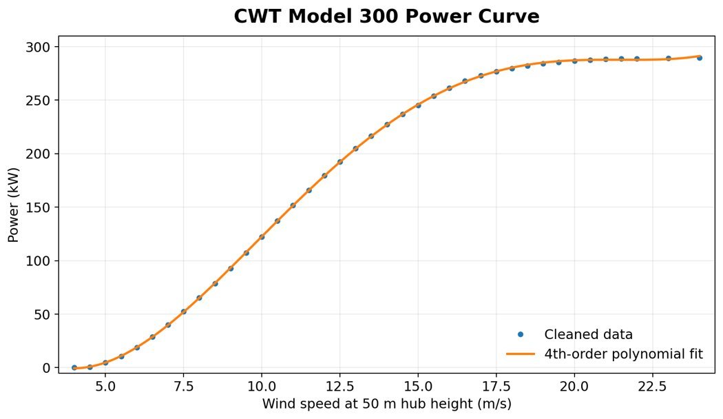
Carter Model-300 Wind Turbines
Guyed-tower · two-bladed teetering hub
TURBINE LOWERED · MAINTENANCE
Tilt-Down Tower Configuration
Guyed-tower advantage — ground-level service access
STEVE CLAMP · NACELLE INSPECTION
Hub & Drivetrain Access
Carter rotor assembly — gearbox, generator, blade root
FEA · VON MISES STRESS · WAKE VORTICES
Aeroelastic Analysis Overlay
Stress concentrations at hub & tower-top · helical wake propagation downwind
SITE INSPECTION · CARTER ROW
Engineer Beside Three Turbines
Guyed-tower configuration · clear-sky inspection
NACELLE & HUB · TOWER-TOP
Drivetrain at Operating Height
Yaw mechanism & rotor hub close-up
60+Turbine Projects
5MW–15MWCapacity Range
Onshore & OffshoreEnvironments
IEC 61400Certified
Rotor & Blade Aerodynamics
BEM theory, full 3D CFD rotor analysis, aeroelastic modelling, and pitch control optimisation. Blade profile selection and airfoil design for maximising annual energy production (AEP).
BEM AnalysisAEP Optimisation
Structural Life Assessment
IEC 61400 fatigue life analysis for blades, tower, and foundation structures. Rainflow counting, Miner's rule application, and damage equivalent load (DEL) calculations for multi-decade service life.
Fatigue LifeDEL Analysis
Offshore Foundation Design
Monopile, jacket, and floating foundation analysis. Combined wind, wave, and current load cases. Soil-structure interaction and scour protection assessment for hostile marine environments.
MonopileMarine Loads
Wind Farm Layout Optimisation
Wake modelling, micrositing, and energy yield assessment. Noise propagation studies, shadow flicker analysis, and ecological impact assessments supporting planning consent.
Wake ModellingMicrositing
West Beacon Farm · Loughborough
Memorable Person · Wind Energy Pioneer
PROFESSOR TONY MARMONT
DSc · DTech · Energy Medal for Lifetime Achievement
Few people did more to bring small and medium wind generation into the UK than Professor Tony Marmont. After making his fortune in soft drinks and plastics, he turned his energy toward renewable generation following the 1970s oil crisis — and quickly recognised that practical, distributed wind power was central to any credible energy transition.
In the early 1990s Tony acquired the rights to the American Carter Wind Turbines technology and backed the establishment of Carter Wind Turbines UK — making it one of the few British-owned companies producing 300 kW class machines. The Carter machines were unusual for their time: two-bladed, soft-tower, downwind designs that prioritised energy capture over conformity to the dominant three-blade European norm. Great Orton wind farm in Cumbria — Britain's only farm of Carter turbines — became the operational legacy of that effort.
Tony then founded Beacon Energy (1992) as a not-for-profit and turned West Beacon Farm near Loughborough into one of the world's most complete working demonstrations of an integrated renewable energy network — combining 25 kWp wind turbines, photovoltaics, ground-source heat pumps, hydrogen storage with electrolysers and fuel cells, hydro generation and CHP, all feeding a common DC bus. He endowed renewable energy research centres at three universities, including CREST at Loughborough, AMSET at De Montfort, and the renewable energy programme at the University of Nottingham.
Steve is honoured to have known Tony as a mentor, collaborator, and friend. His pragmatic, evidence-led approach to wind turbine engineering — and his refusal to be deterred by conventional wisdom — remain a constant influence on the rotor and blade work represented in this section.
Carter Wind Turbines UKGreat Orton Wind FarmBeacon Energy · 1992West Beacon FarmCREST LoughboroughEnergy Institute Award 2009
Memorable People
People Who Shaped This Work
This section is dedicated to the remarkable individuals — colleagues, mentors, clients, and collaborators — whose expertise, vision, and partnership contributed to the projects and programmes represented here. Their names and stories will be added over time.
Content coming soon. Contact info@steveclamp.com to contribute a memory or nomination.
Hybrid Systems · Grid Integration · User Tuned Fuel · Scrub CO₂ from the environment
The energy transition demands engineers who can think across boundaries. Steve synthesises aerospace systems engineering rigour with deep energy sector knowledge to design and optimise complex multi-source energy architectures.
GW-scaleProjects Reviewed
H₂Green Hydrogen
BESSStorage Systems
Net ZeroStrategy Support
Hybrid Energy System Design
Architecture and sizing of multi-source energy systems combining wind, solar PV, tidal, and battery storage. Dispatch optimisation, reliability analysis, and LCOE modelling.
Hybrid PV/WindLCOE Model
Hydrogen & Fuel Cell Systems
Green hydrogen production via electrolysis, compression and storage systems, and fuel cell integration for both stationary power and transport applications including aviation.
ElectrolysisPEM Fuel CellsH₂ Aviation
Grid Integration & Stability
Power electronics, grid code compliance, frequency and voltage support from renewable assets. Grid-forming inverter studies and virtual synchronous machine (VSM) modelling.
Grid CodeVSM Studies
Sustainable Aviation Fuels
SAF pathway analysis, lifecycle emissions assessment, and integration challenges for commercial aviation. Policy landscape navigation and fleet transition planning support.
SAF PathwaysLCA / GHG
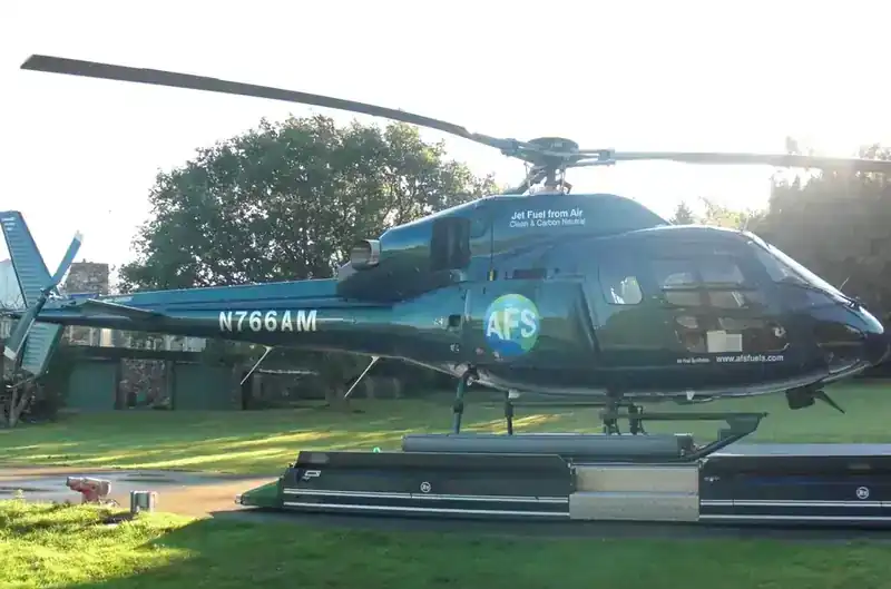
Fuel From Air · UK Pilot Plant & USA Renewable-Powered Development
PIONEERING FUEL SYNTHESIS FROM ATMOSPHERIC CARBON
With Professor Tony Marmont · Solar & Wind Powered · BBC Feature
Professor Tony Marmont pioneered the concept of fuel from air — the synthesis of carbon-neutral liquid hydrocarbon fuels by capturing carbon dioxide directly from the atmosphere and combining it with hydrogen produced via electrolysis from renewable electricity. He funded and supported the development of a pilot plant in the UK that demonstrated the full air-to-fuel pathway end to end, showing that synthetic petrol could be produced using nothing but air, water and renewable power.
Steve and Tony went on to explore development of the technology in the USA, utilising solar and wind as the primary sources of electrical power for the plant. The American development built on the proven UK pilot architecture and assessed scaling pathways under the very different solar resource, wind regimes, regulatory landscape and fuel-market economics of the United States.
The BBC produced a trailer for the programme, included in the main business website. Visit www.fuelfromair.com for the BBC trailer and to learn more about the project.
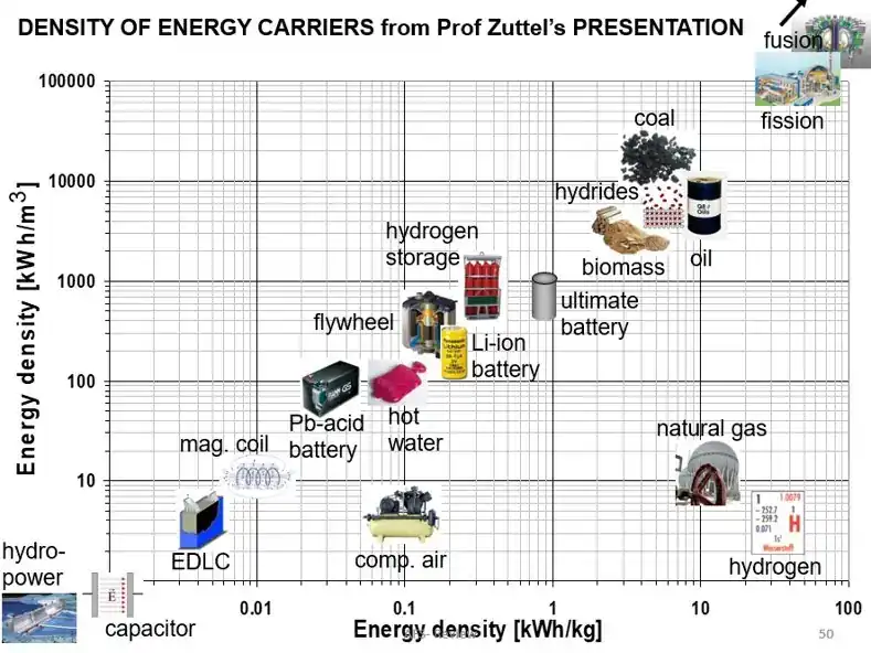
Synthetic liquid fuel made from air and water is, fundamentally, stored electricity. Each litre of diesel, gasoline (petrol) or kerosene carries a fixed amount of chemical energy, and producing it from atmospheric CO₂ and water via electrolysis and Fischer–Tropsch synthesis costs a multiple of that energy in electricity. Enter your electricity price to estimate the electricity cost per unit volume of each fuel, and how much fuel a single kilowatt-hour can make.
Inputs
Electricity Price
Currency
Volume Unit
Process Efficiency 45%
Electricity → liquid fuel, well-to-tank
Calculated Results
Electricity Cost per Litre
Fuel Volume Produced per kWh
Basis & Assumptions
Fuel energy content uses lower heating value (LHV). Diesel ≈ 9.94 kWh/L (0.832 kg/L), gasoline/petrol ≈ 8.89 kWh/L (0.745 kg/L), kerosene/Jet A ≈ 9.48 kWh/L (0.800 kg/L). Electricity required per unit = fuel LHV ÷ process efficiency. US gallon = 3.78541 L. The efficiency slider represents the whole electricity-to-liquid chain (electrolysis, CO₂ capture, Fischer–Tropsch and upgrading); real air-to-fuel plants typically land in the 40–50% range. Figures show the electricity cost component only — capital, CO₂ capture and operating costs are excluded.
Pairing the Carter Wind Technology Model 300 (a 300 kW turbine) with the air-to-fuel pathway turns a single turbine into a standalone synthetic-fuel plant. Enter the turbine purchase price and your site's average wind speed; the calculator reads the Model 300 power curve below, estimates annual energy capture using a Rayleigh wind distribution, and converts that energy into litres (or gallons) of diesel, gasoline and kerosene per turbine per year — using the same LHV and process-efficiency assumptions as the Fuel Production Estimate tab.
Inputs
Avg Wind Speed (m/s)
Turbine Purchase Price
Currency
Volume Unit
Capital Payback (yrs)
Process Efficiency 45%
Turbine Energy Capture
Annual Fuel Produced per Turbine
CWT Model 300 Power Curve
Annual Fuel Volume per Turbine
Capital + Maintenance Cost per L — 10 Year Profile
Analysis
Basis & Assumptions
Power output follows a 4th-order polynomial fit to the CWT Model 300 power curve shown above (cut-in 4 m/s, rated ≈290 kW, cut-out 24 m/s). Annual energy is estimated by integrating the power curve against a Rayleigh wind-speed distribution whose mean equals the entered average wind speed, over 8,760 hours/year. Fuel conversion uses the same lower-heating-value figures as the Fuel Production Estimate tab (diesel 9.94, gasoline 8.89, kerosene 9.48 kWh/L) and the same electricity-to-liquid efficiency slider. US gallon = 3.78541 L. CO₂ absorbed and O₂ released are from the synthesis stoichiometry (x CO₂ + (y/2) H₂O → CₓHₐ + (x+y/4) O₂) using representative fuel formulas (diesel/kerosene ≈ C₁₂H₂₃, gasoline ≈ C₈H₁₈): ≈2.3–2.6 kg CO₂ absorbed and ≈2.6–2.8 kg O₂ released per litre. The carbon is re-emitted when the fuel is burned, so the cycle is carbon-neutral, not net-negative. Cost-per-unit figures reflect turbine capital recovered over the first 3 years (purchase price ÷ 3, per year) plus a 5% annual maintenance fee on the purchase price; after year 3 the capital is repaid and only the 5% maintenance remains. The 10-year profile shows this drop. Electrolysis, CO₂ capture, balance-of-plant and feedstock costs are excluded. Indicative engineering estimate only.
West Beacon Farm · Loughborough
Memorable Person · Mentor & Pioneer
PROFESSOR TONY MARMONT
DSc · DTech · Energy Medal for Lifetime Achievement
Professor Tony Marmont was a British renewable energy pioneer whose vision and generosity helped lay the foundations of the UK's modern sustainable energy research base. Having built his fortune in the soft drinks and plastics industries, he turned his energies after the 1970s oil crisis to the cause that would define the rest of his life — averting man-made climate change through practical, integrated renewable energy.
In 1992 Tony founded Beacon Energy as a not-for-profit organisation, and turned West Beacon Farm near Loughborough into one of the world's most complete working demonstrations of an integrated renewable energy network — combining wind turbines, photovoltaics, ground-source heat pumps, hydrogen storage with electrolysers and fuel cells, hydro generation, and CHP, all feeding a common DC bus. He endowed and helped establish renewable energy research centres at three universities, including CREST at Loughborough, AMSET at De Montfort, and supported the renewable energy programme at the University of Nottingham.
As a co-founder and major backer of Air Fuel Synthesis, Tony helped pioneer the production of synthetic, carbon-neutral transport fuel directly from atmospheric CO₂ and water — a breakthrough demonstration that the production laboratory now operates as Fuel from Air Ltd at West Beacon Farm. His belief that civilisation could be re-engineered to leave fossil fuels behind, combined with the willingness to fund the research that proved it, shaped a generation of engineers and policy makers.
Steve is honoured to have known Tony as a mentor, collaborator, and friend. His clarity of purpose, technical curiosity, and refusal to leave any stone unturned remain a constant influence on the energy synthesis work represented in this section.
Beacon Energy · 1992West Beacon FarmAir Fuel SynthesisCREST LoughboroughAMSET De MontfortU. NottinghamEnergy Institute Award 2009
Memorable People
People Who Shaped This Work
This section is dedicated to the remarkable individuals — colleagues, mentors, clients, and collaborators — whose expertise, vision, and partnership contributed to the projects and programmes represented here. Their names and stories will be added over time.
Content coming soon. Contact info@steveclamp.com to contribute a memory or nomination.
Modern aerospace engineering is inseparable from its digital tools. Steve is proficient across the complete engineering software stack and has developed bespoke analysis tools deployed operationally within major aerospace programmes.
FeToolKit provides structural analysis tools for aerospace and mechanical engineers to enhance their production, solution and reporting of complex mathematical engineering problems. The platform delivers a graphical interface with intuitive menus, drawing on engineering materials, methods, standards and regulatory practice to assess structural integrity.
FeToolKit acts as a pre-processor for all major finite element systems, with extensive post-analysis processing capability to extract, manipulate and solve complex engineering problems. Built-in standards include NASA STD 5020, NASA NSTS 08307, NASA Joint 4, HSB 63120-01, MSPC 486B, and supplier-specific manuals from Airbus, Boeing and Rolls-Royce.
The toolkit also includes extensive MRB composite assessment tools — Material Review Board workflows for laminate defect, buckling, bond-line repair, scarf repair, perforated damage and joint stiffness — engineered to speed up production support and reduce the time from defect discovery to disposition.
Visit the FeToolKit website for the full module list, screenshots, and licensing information.
This section is dedicated to the remarkable individuals — colleagues, mentors, clients, and collaborators — whose expertise, vision, and partnership contributed to the projects and programmes represented here. Their names and stories will be added over time.
Content coming soon. Contact info@steveclamp.com to contribute a memory or nomination.
ENGINEERING MECHANICS
Stephen Timoshenko
Father of modern engineering mechanics
SWANSEA · FEM PIONEER
Olgierd (Olek) Cecil Zienkiewicz
18 May 1921 – 2 January 2009 · Elected FRS 1978 · Swansea
SWANSEA · FINITE ELEMENTS
Ernie Hinton
Finite element method · Swansea
ROLLS-ROYCE · CALGARY
Bruce Irons
FE pioneer · Rolls-Royce and Calgary
Section 07
ENGINEERING CONSULTANCY
Strategy · Reviews · Compliance · Management
Steve provides strategic consultancy to aerospace businesses, government agencies, and investment firms. His independent technical authority status, programme management experience, and cross-discipline knowledge make him a trusted partner for high-stakes engineering decisions.
200+Clients Served
ITAAuthority Status
£BnProjects Reviewed
ExpertWitness Work
Independent Technical Review
Independent design reviews, critical design reviews (CDR), and test readiness reviews across all aerospace disciplines. Impartial technical authority providing confidence to programme stakeholders.
CDR / TRRITA Services
Program & Project Management
Earned value management, risk register development, and integrated master schedule creation. WBS development, contract review, and supplier technical oversight for complex multi-partner programmes.
EVMRisk Management
Regulatory & Certification Support
Navigation of EASA, FAA, CAA, and international airworthiness authority requirements. Certification plans, compliance demonstration, and liaison with regulatory bodies on novel designs.
EASA / FAACert Plans
Investment & Due Diligence
Technical due diligence for aerospace investment and M&A transactions. Technology readiness level (TRL) assessment, IP analysis, and manufacturing readiness evaluation for investor clients.
TRL AssessmentDue Diligence
Selected Projects · Career Portfolio
Independent Consultancy · Multi-Sector
REPRESENTATIVE PROJECT PORTFOLIO
Aerospace · Space · Marine · Civil · Rail · Automotive · Energy
22
Listed Projects
7
Industry Sectors
Aerospace — Military & Government
Netherlands Royal Air Force
Fokker F27 'Vinton' Electronic Counter Measures wing pod stress analysis
Government of India
Surveillance and Interdiction Embraer 190 radar modification approval
UK Royal Air Force
AV-8B Harrier elevator fly-by-wire airworthiness approval
UK Royal Air Force · HM Queen's Flight
HS748 Andover anti-missile pod design
Royal Dutch Airforce
Vinten pod addition, fuselage and frame analysis
Aerospace — Commercial & Cargo
Marshalls Cambridge
Hercules C-130 main oleo fracture analysis
Hunting Aircraft
Design and certification of TU-134 interior redesign
Britten-Norman
British Army Islander fuselage modification
British Aerospace
HS146 / AS900 engine pylon structural analysis
Lighter-Than-Air
Virgin · Richard Branson & Per Lindstrand
Around-the-world record attempt — structural and design approval of balloon, catenary and pressurised capsule
Cameron Balloons
Structural analysis and design optimisation of commercial pleasure balloons
Balloon Fire Egress Safety
Design and structural approval of cable escape system
Fuel station structural steel analysis and certification
Lloyd's Register, London
Offshore oil rig tension-leg cable analysis
Lloyd's Register, London
Offshore oil rig deck and leg structure — certification
Automotive, Rail & Ground Defence
British Rail
CL318 locomotive chassis dynamic and impact analysis
UK British Army
Mobile pontoon bridge structural analysis
Jaguar Motors
X-Type car chassis noise and vibration structural analysis
Energy & Government
UK Government
Wind and solar power — renewable energy consultant
This list is a selected, non-exhaustive sample of consultancy work undertaken across more than three decades. Many additional projects are covered by confidentiality, non-disclosure or program-classification restrictions and are not listed here. References are available on request to qualifying enquiries.
Engage Steve
Whether you need an independent technical review, a forensic engineering investigation, or strategic advice on an aerospace venture, Steve's consultancy delivers rapid, high-quality outputs within your programme schedule. Contact: info@steveclamp.com
Engineering Research
Research & Development
Steve's engineering research spans structural mechanics, composite materials, computational methods, and novel analysis techniques developed across decades of applied aerospace engineering. This section documents published research, technical papers, patent work, and methodology contributions to the engineering community.
Research content will be added here. Contact info@steveclamp.com for research enquiries and collaboration.
Structural Mechanics Research
Development and validation of analytical methods for complex structural joints, tension fittings, composite laminates, and aeroelastic problems — methods now applied fleet-wide on Boeing commercial aircraft programmes.
Structural JointsTension FittingsFleet Methods
Composite & FEA Methods
Research into ply-by-ply composite laminate analysis, MRB damage assessment, bond line repair methodologies, and finite element techniques for thin-shell and solid CFRP structures — embodied in FEToolKit and applied at FACC Austria.
CFRP AnalysisMRB MethodsFEToolKit
Lighter-Than-Air Structures
Research into non-rigid airship structural analysis — envelope membrane theory, gondola pressure vessel analysis, suspension cable systems, and aerodynamic load distribution — contributing to the CAA certification of the Skyship 600.
Membrane TheoryLTA StructuresCAA Certification
Memorable People
People Who Shaped This Work
This section is dedicated to the remarkable individuals — colleagues, mentors, clients, and collaborators — whose expertise, vision, and partnership contributed to the projects and programmes represented here. Their names and stories will be added over time.
Content coming soon. Contact info@steveclamp.com to contribute a memory or nomination.
Engineering Consultancy · India
India Design Office
A new design and stress analysis office established in Chandigarh, North India, extending engineering capacity for aerospace structural analysis and design work.
Opening Ceremony
Opening Pujah
The new office was inaugurated with an opening pujah — a traditional blessing ceremony — led by the chief engineer, marking the start of design and stress analysis operations in Chandigarh.
ChandigarhNorth IndiaDesign OfficeStress Analysis
Section 08 — Research & Development
ENGINEERING RESEARCH
Applied R&D · Methods · Innovation
🔒
Restricted — Authorisation Required
This research content is protected. Enter your authorisation code to view it.
Tree Stress — Wind Loading of a Tapered Cantilever
A tree in wind is a vertical cantilever. Wind drag on the crown, F = ½ ρ Cd A v², acts at the crown’s centre of pressure and bends the trunk. At the base this produces a bending moment M = F·hcp, a peak bending stress σ = M/Z and a peak shear stress τ at the neutral axis. A trunk is not solid — the load-bearing sapwood forms a hollow tube (annular section), so Z = π(D⁴−d⁴)/32D and A = π(D²−d²)/4 for outer diameter D and bore d. Because stiffness scales with r⁴, a tube keeps almost all its strength using far less wood. Pick a species, then vary wind speed and tree age — the tree sways, and the base cross-section shows the tension–compression bending gradient and the parabolic shear. Green wood modulus of rupture (MOR) sets the failure threshold and safety factor. Real crowns streamline (reconfigure) in strong wind, so field drag grows more slowly than v² — treat these as conservative upper-bound estimates.
Tree Species
Wind Speed
80km/h
Tree Age
80 yr
Hollow Core (bore d/D)
0.40(0=solid)
Units
English Oak · Wind Deflection
Base Cross-Section — Stress Distribution
Base Bending Stress vs Wind Speed
9.9 kN
Wind Drag F
138 kN·m
Base Moment M
2.7 MPa
σ Bending
0.02 MPa
τ Shear
18.5
Safety Factor
Interactive Calculator
Car Impact — Occupant & Cervical-Spine Loads (Frontal Rigid Barrier)
A belted occupant “rides down” the crash as the front structure crushes. Mean occupant deceleration a = v²/2d, where d is the effective ride-down distance (crumple + restraint). Whole-body inertial force is F = m·a; in body-weights this equals the g-level. The head (≈4.5 kg) must be decelerated by the neck: as it pitches forward through angle θ, the cervical load resolves into an axial force Fz = mha·cosθ, a shear Fx = mha·sinθ, and a flexion bending moment My = mha·L about the occipital condyles. The neck-injury index Nij = Fz/Fzc + My/Myc uses FMVSS 208 critical intercepts (Fzc=6160 N compression, Myc=310 N·m flexion); Nij ≥ 1 indicates a significant injury risk. This is a simplified rigid-body engineering estimate for a belted 50th-percentile male — not a medical prediction; real outcomes depend on pulse shape, airbag timing and intrusion.
Steve's career is underpinned by exceptional academic education, recognised professional status, and a record of industry recognition spanning four decades of aerospace innovation. Steve is committed to supporting future generations of engineers.
Publications & Presentations
Steve has authored or co-authored over 16 peer-reviewed technical papers. He has delivered keynote addresses at the Aerospace Engineering Annual Conference. He is a named inventor on 3 patents and holds directorship in no less than 5 international engineering businesses.
Steve and His First Aeroplane
Steve and his first aeroplane — Cessna 150H, Cambridge, UK.
🔒
Restricted — Authorisation Required
This content is protected. Enter your authorisation code to view it.
Unmanned Aerial Vehicles · Autonomous Systems · MALE · HALE
FLAGSHIP HEXAROTOR 🔒
NXYWING 200
N500 · FIXED-WING 🔒
NXYWING 500
JET-POWERED 🔒
NXYWING 2000
NXYWING — UK BASED UAV OPERATIONS
Hexacopter Platform — Multi-Rotor UAV with EO/IR Payload
Development · Manufacture · Operation of Unmanned Remote Platforms
NXYWING is a totally owned business of Steve and is based in Scottsdale, Arizona, United States. The company origins can be tracked back to Derbyshire, United Kingdom. Steve has been involved in the development, manufacture and operation of unmanned remote platforms for many years — combining cutting-edge aerodynamic design with robust structural engineering principles Steve has applied across decades of certified aerospace programmes.
Unmanned aerial vehicles represent one of the most demanding intersections of aerospace engineering disciplines — combining lightweight structural design, autonomous flight systems, long-endurance aerodynamics, and mission payload integration. Steve brings decades of fixed-wing structural analysis and aerodynamic expertise directly to the UAV sector, supporting both military and civilian programmes from concept through certification.
On the NXYWING platforms, Steve's role spanned design support, detailed stress analysis, development & qualification testing, and certification / permits to fly.
MALE/HALEPlatform Types
24hr+Endurance Design
Multi-RolePayload Capability
STANAGInteroperability
Structural Design & Analysis
Lightweight airframe structural design for UAV platforms operating across the full flight envelope. Composite wing and fuselage stress analysis, fatigue life assessment, and aeroelastic tailoring to optimise stiffness-to-weight ratios for long-endurance missions.
Composite StructuresAeroelastic TailoringFatigue Life
Aerodynamic Performance
High-aspect-ratio wing aerodynamics for HALE platforms, low Reynolds number airfoil analysis for small UAVs, and propulsion integration. Mission profile optimisation including loiter efficiency, cruise speed trade studies, and multi-segment flight plan analysis.
High-AR WingsLow Re AirfoilsLoiter Optimisation
Payload & Systems Integration
Structural accommodation of EO/IR sensor turrets, SAR radar arrays, SIGINT antennae, and weapons pylons. Centre-of-gravity management across payload configurations, vibration isolation mounting design, and electromagnetic compatibility considerations.
EO/IR TurretsSAR IntegrationPylon Loads
Certification & Airworthiness
UAV airworthiness certification to DEF STAN 00-970, EASA SC-RPAS, and civil CAA frameworks. Military release-to-service documentation, continued airworthiness programmes, and support to STANAG 4671 compliance for NATO interoperability.
DEF STAN 00-970EASA SC-RPASSTANAG 4671
Ground Control & Data Links
Ground control station (GCS) human factors review, data link margin analysis, and lost-link contingency structural assessment. Beyond visual line of sight (BVLOS) operational safety case support and airspace integration analysis.
GCS DesignBVLOSSafety Case
Launch, Recovery & Logistics
Catapult launch structural load analysis, net and runway recovery system loads, undercarriage design for semi-prepared surfaces, and rapid-deployment packaging design for forward-deployed operations. Reliability and maintainability (R&M) analysis.
Launch LoadsRecovery SystemsR&M Analysis
UAV Program Consultancy
Steve's aerospace engineering background — spanning certified fixed-wing aircraft, composite structures, FEA/CFD analysis, and airworthiness certification — translates directly into the demands of modern UAV programs. From small tactical systems to large strategic HALE platforms, his structural and aerodynamic analysis capability provides programme teams with independent verification and certification support that meets both military and civil airworthiness authority expectations. Whether supporting a new type design, a major modification, or an airworthiness investigation, Steve's UAV consultancy delivers engineering rigour proportionate to the risk and mission requirement.
🔒
Restricted — Authorisation Required
This NXYWING content is protected. Enter your authorisation code to view it.


 www.carterwindsolutions.com
 www.fuelfromair.com
 www.fetoolkit.com
 www.nxywing.com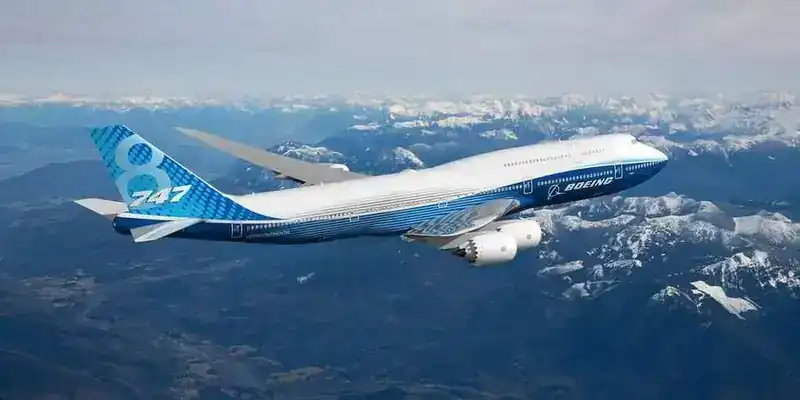
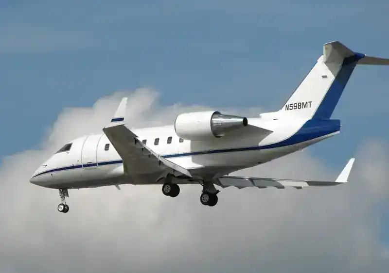
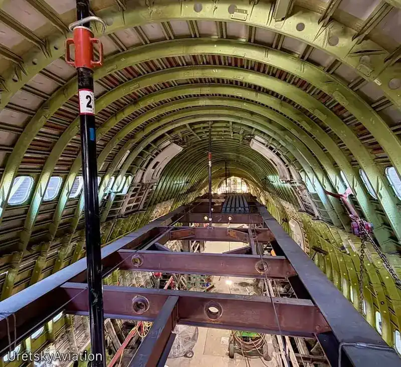
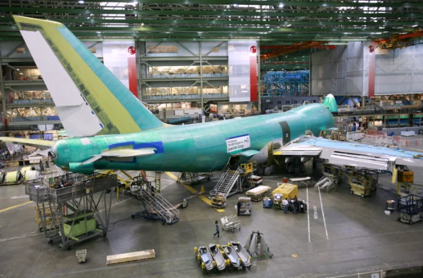
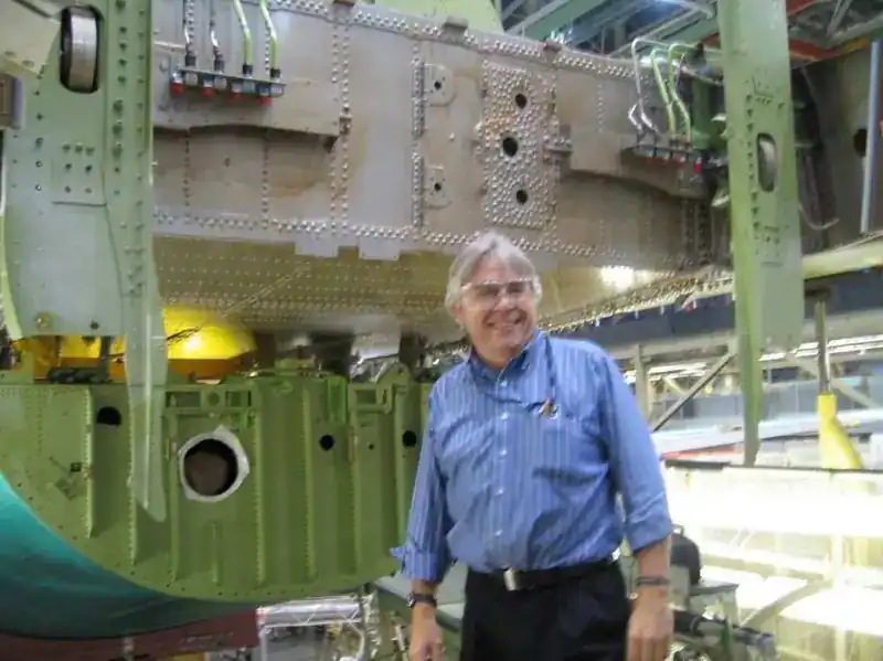
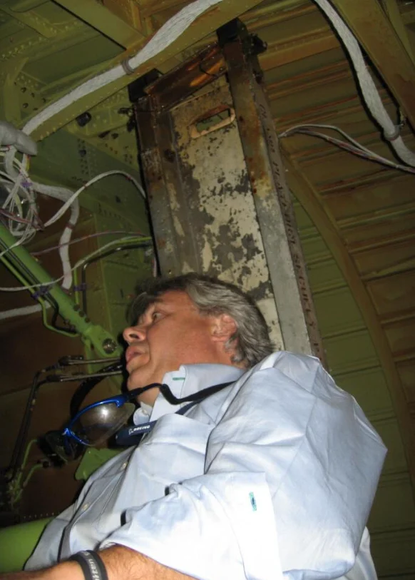
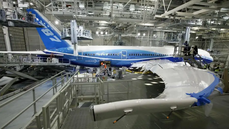
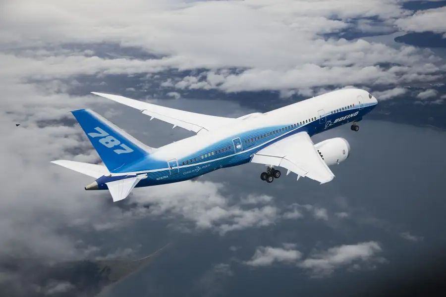
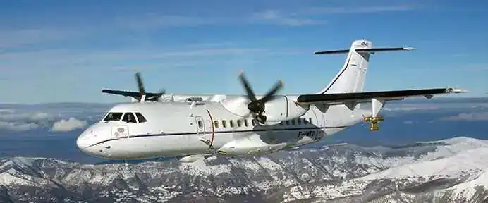
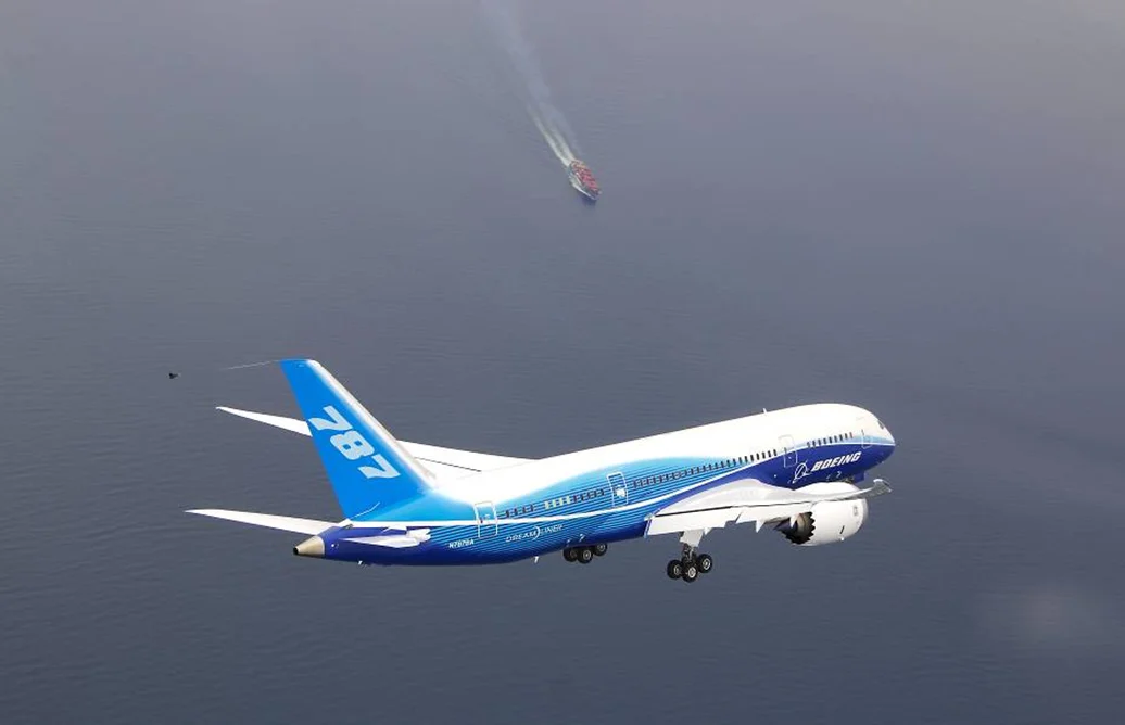
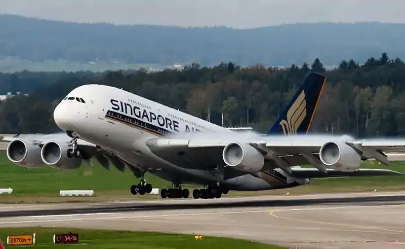
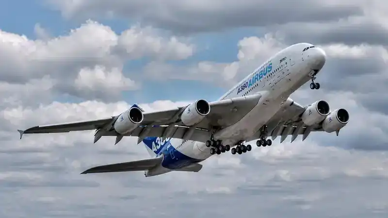
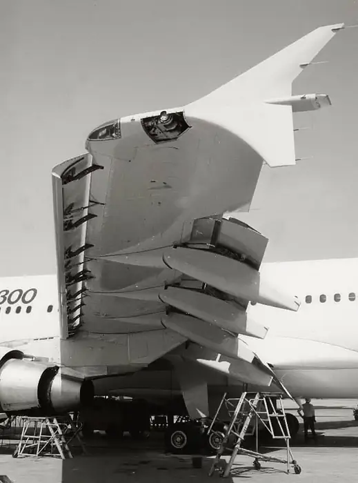
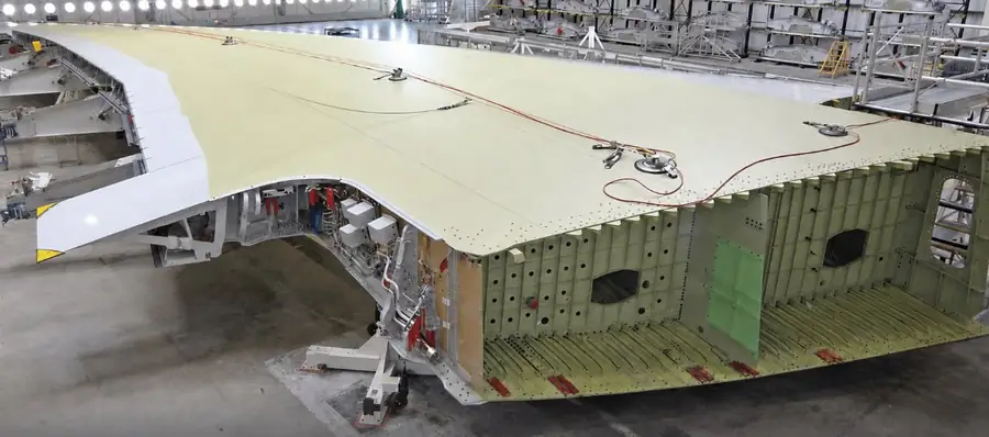
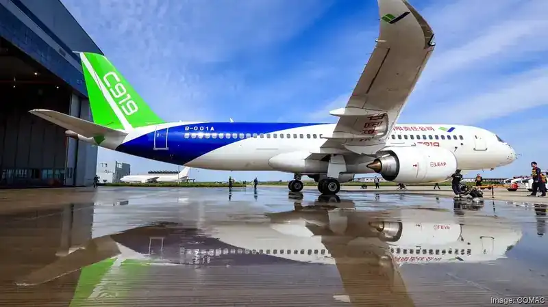
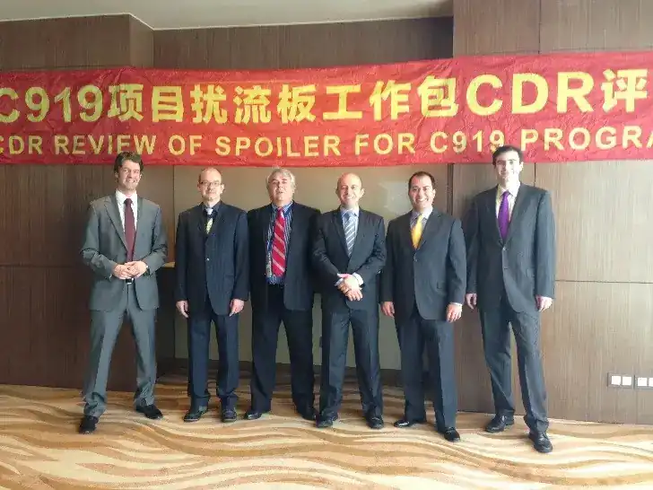
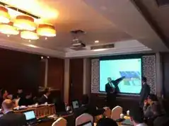
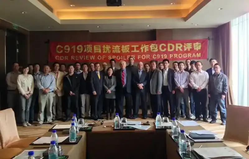
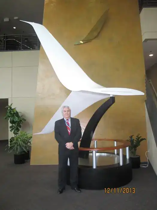

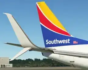

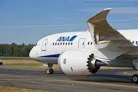
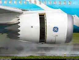
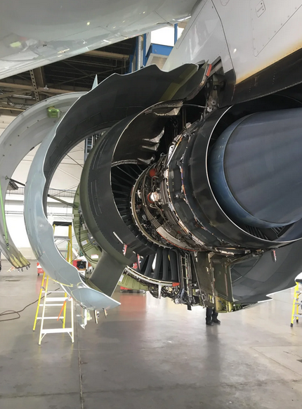
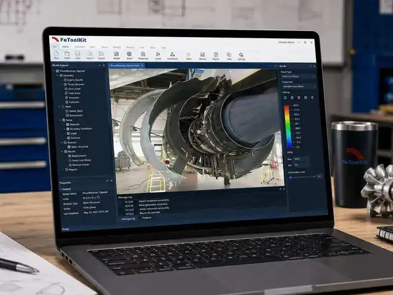
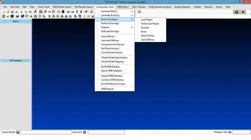
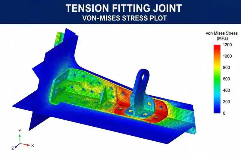
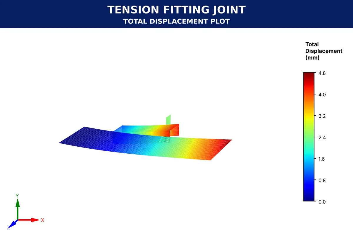
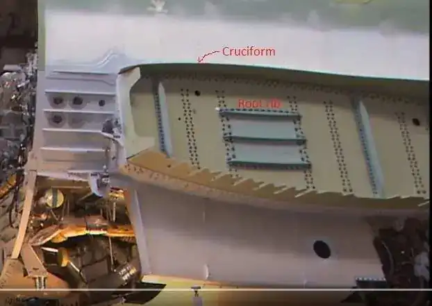
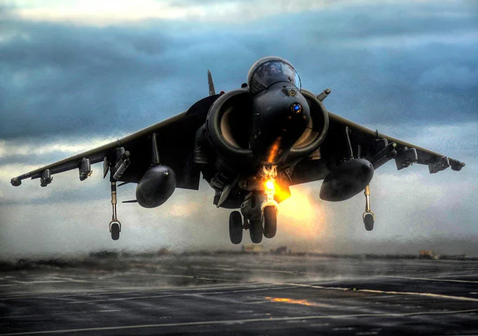
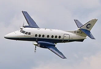
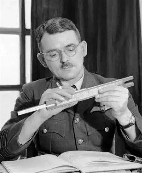
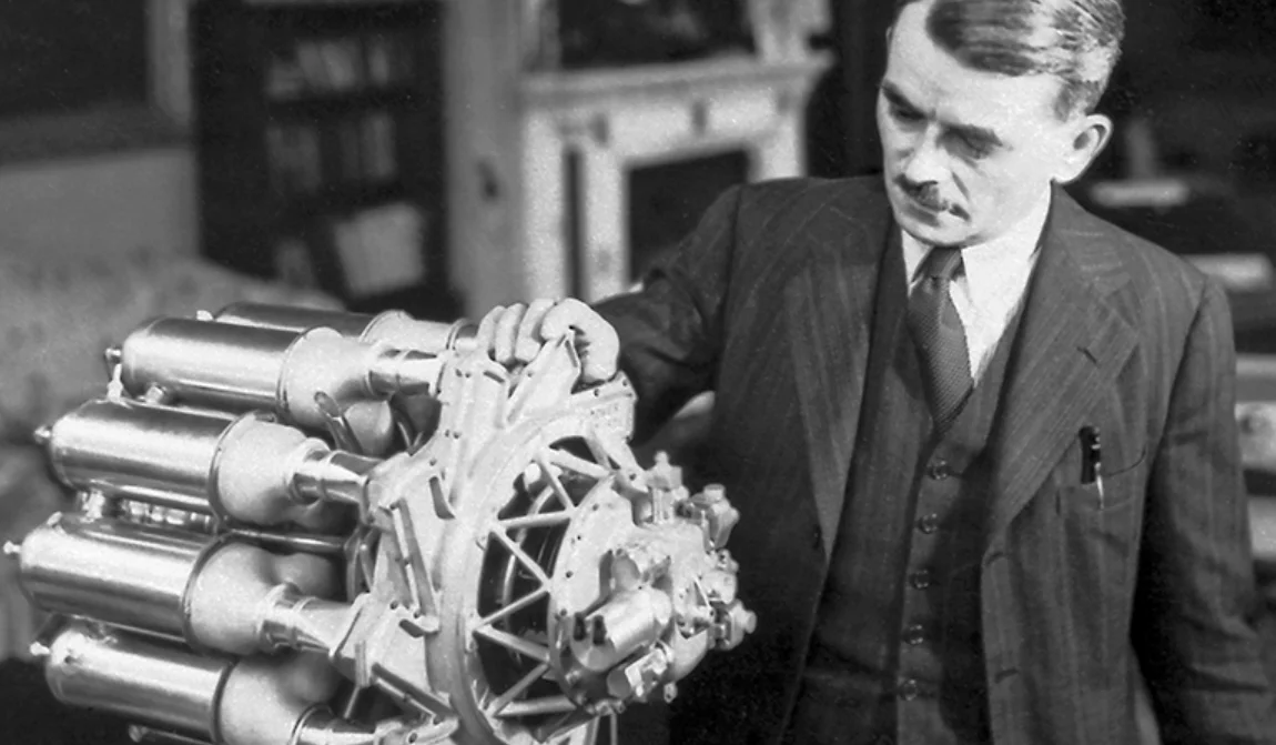
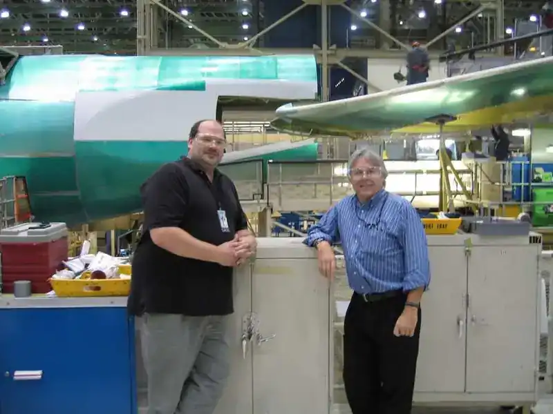
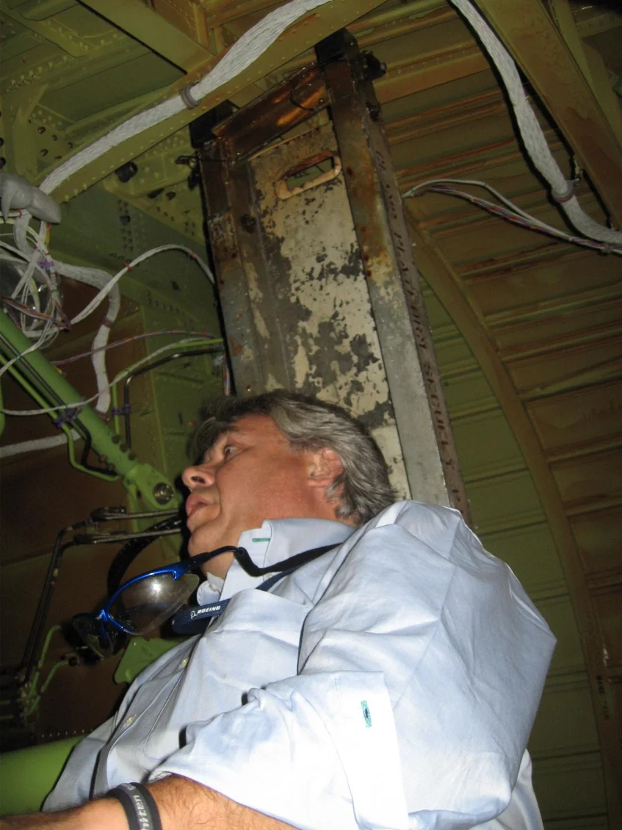
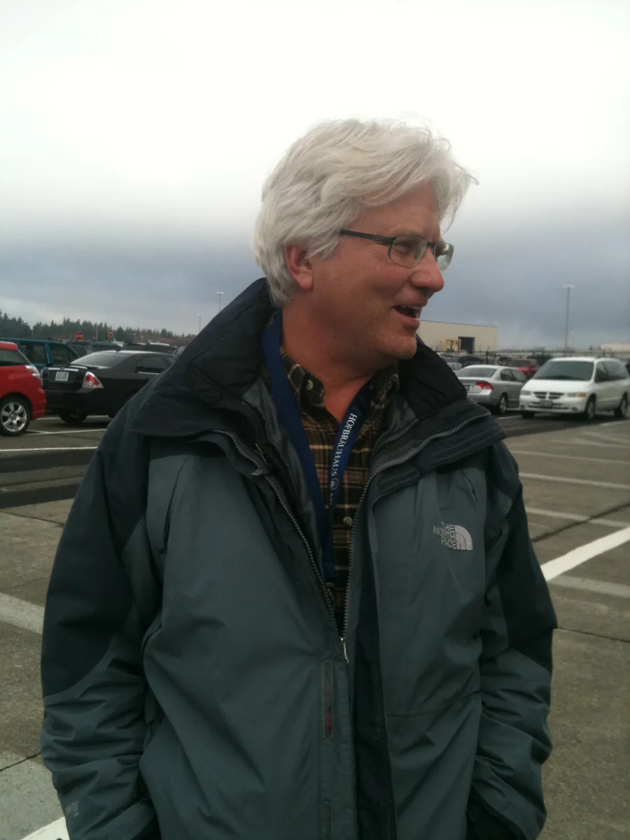
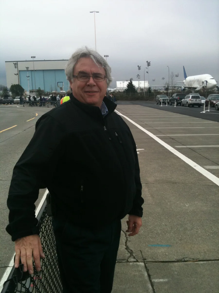
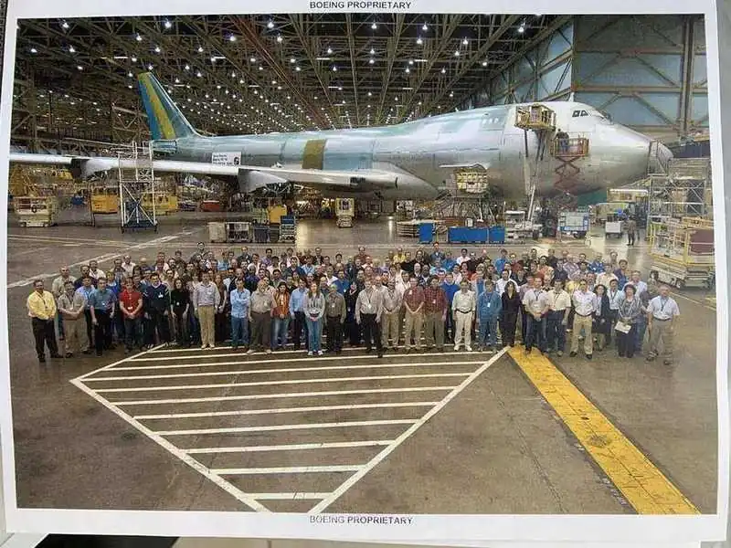
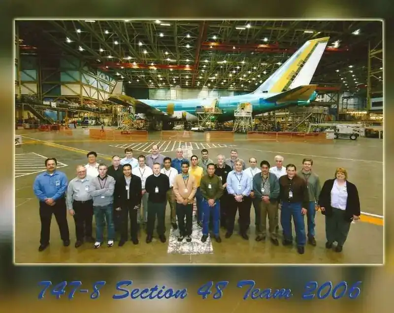
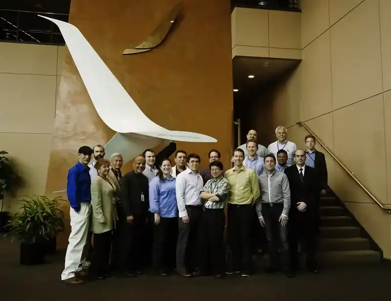
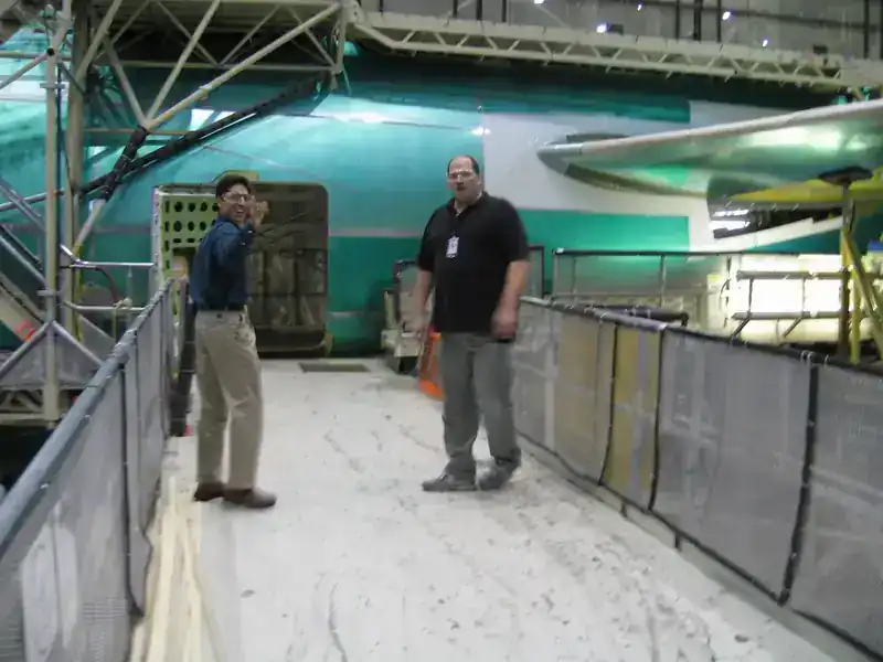
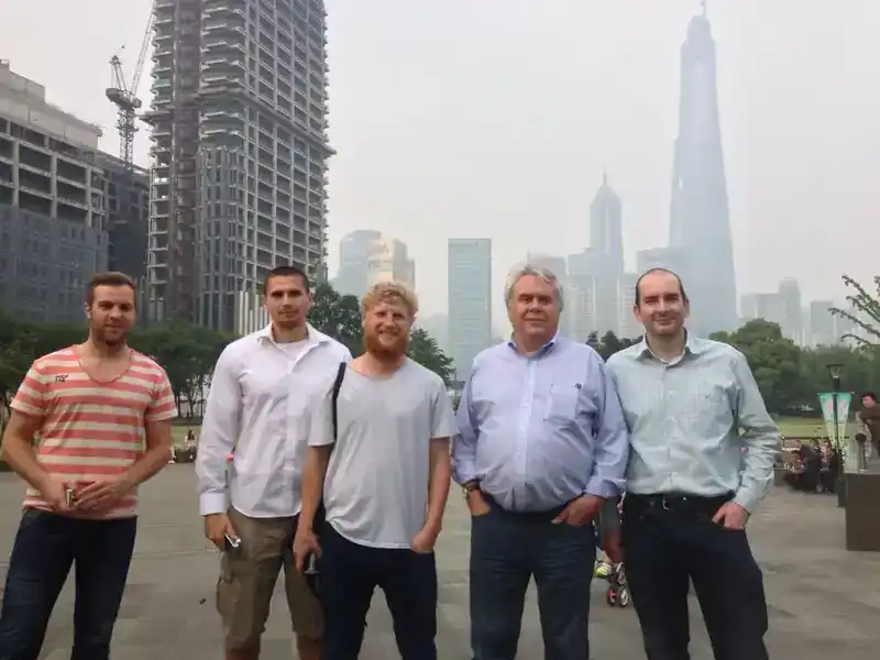
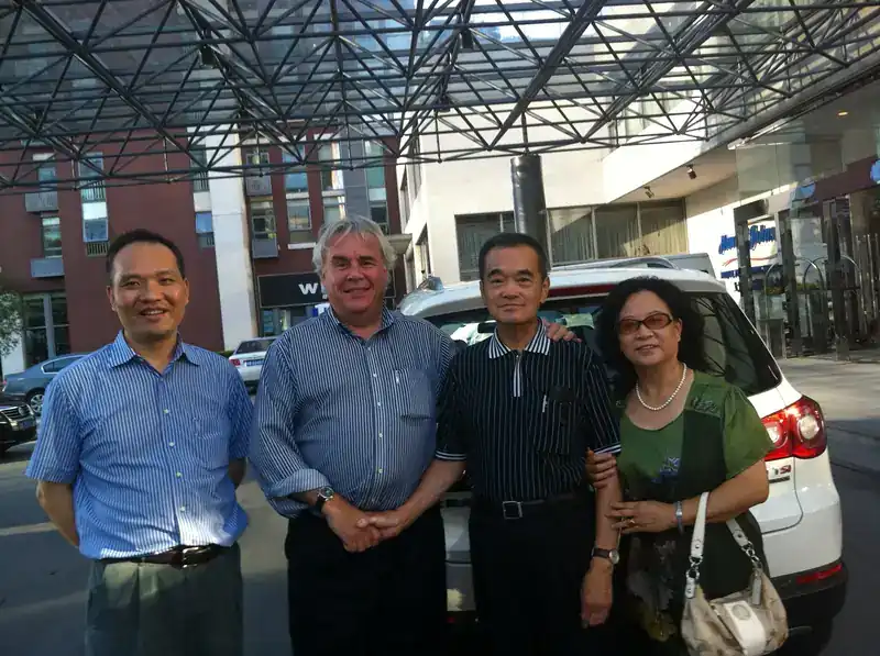
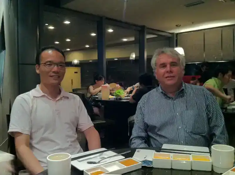
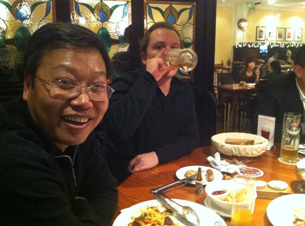
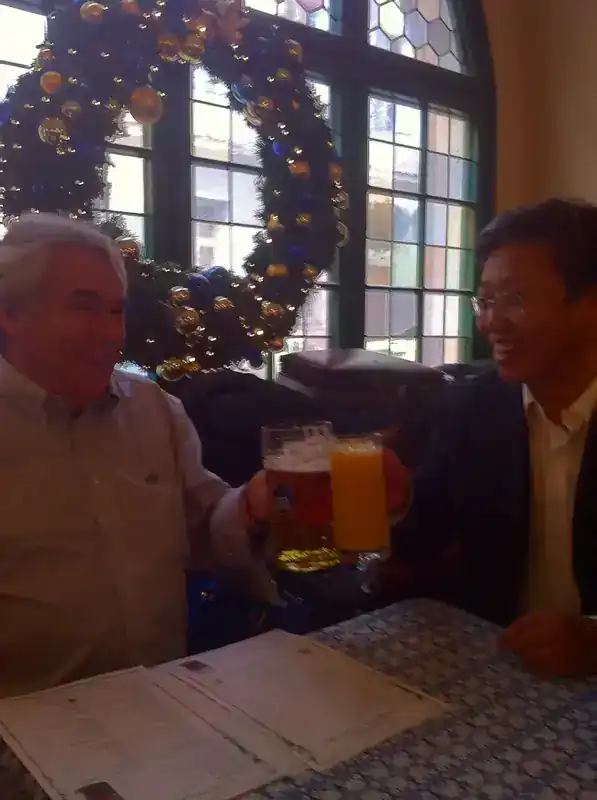
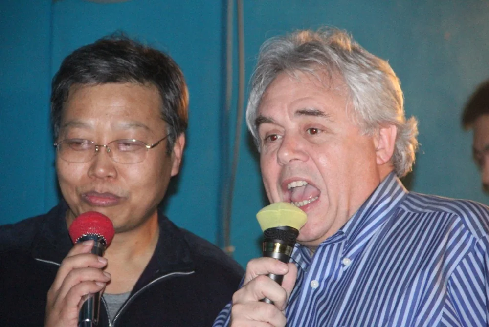
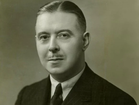
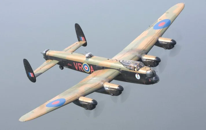
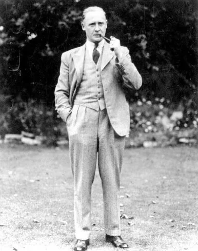
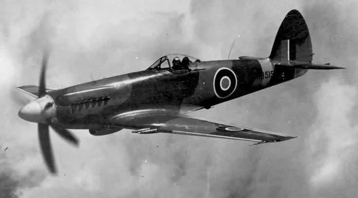
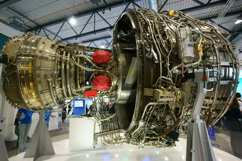
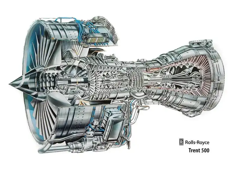
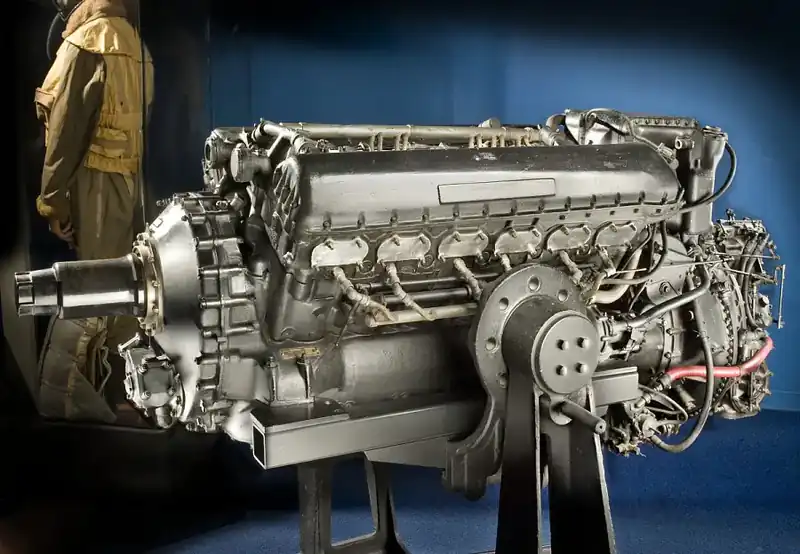

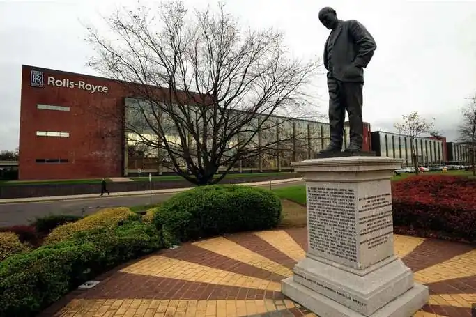
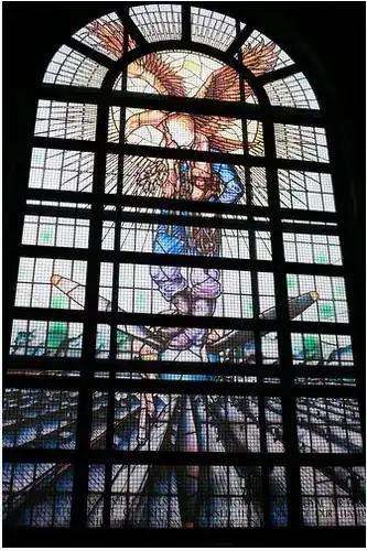
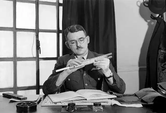
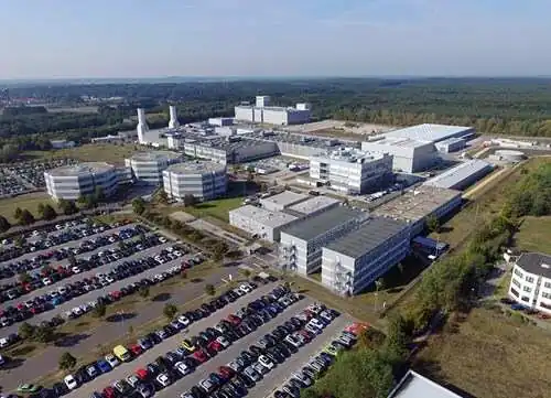
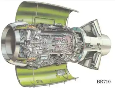
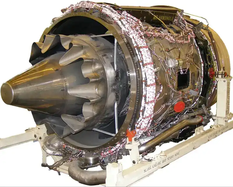

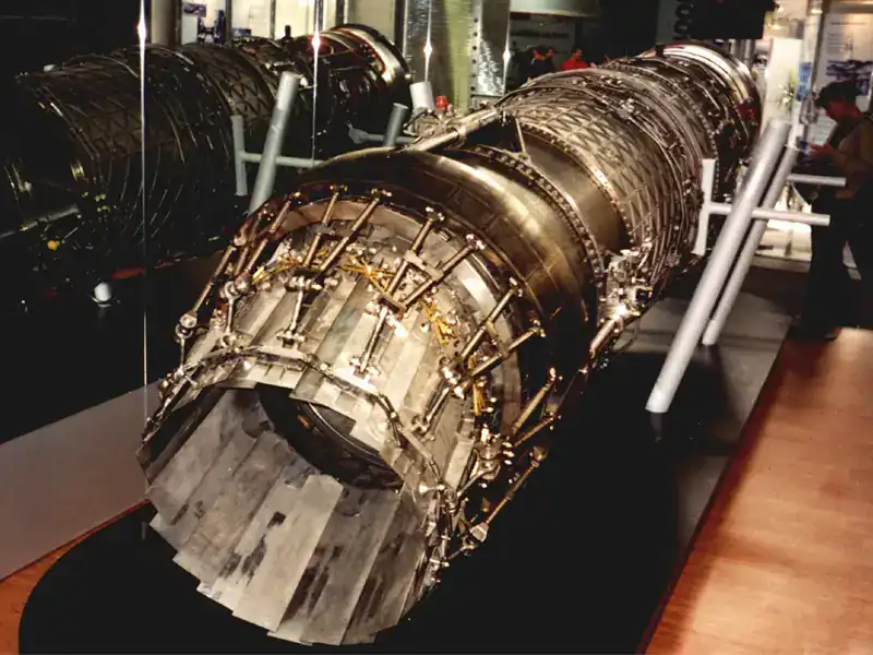
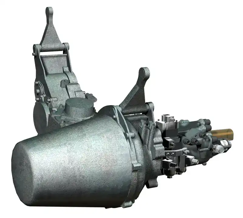
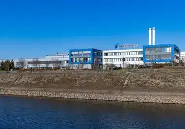
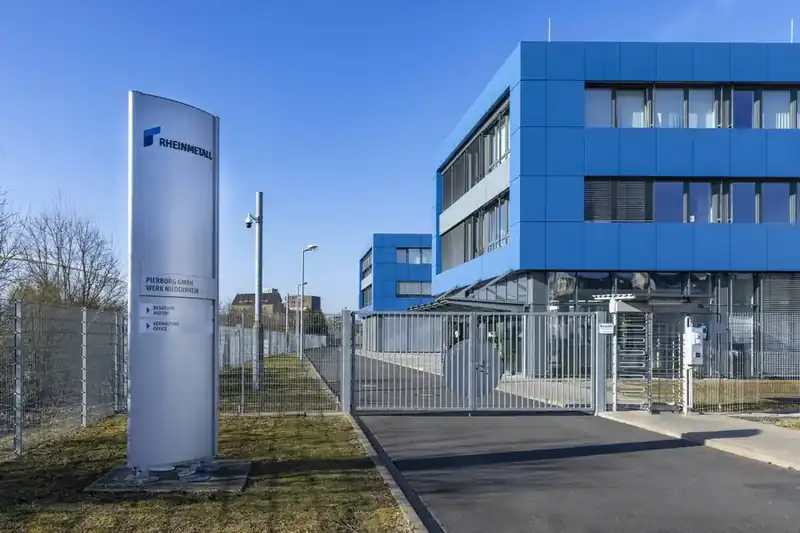
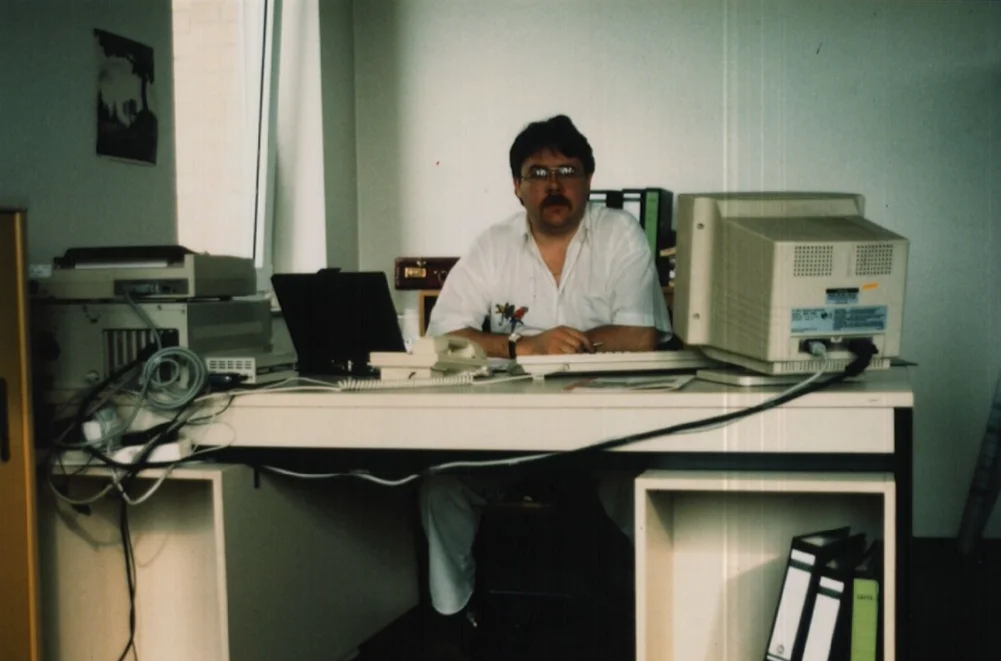
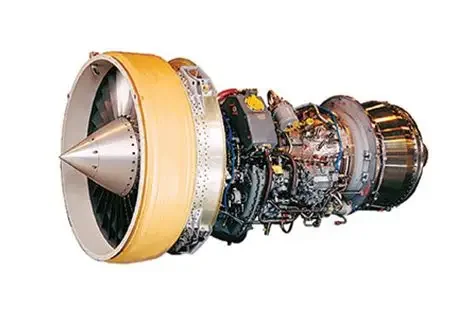
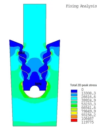
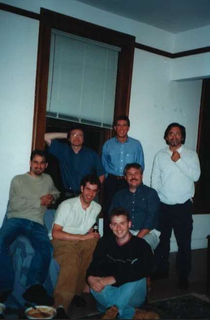
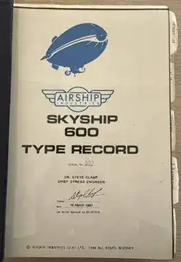
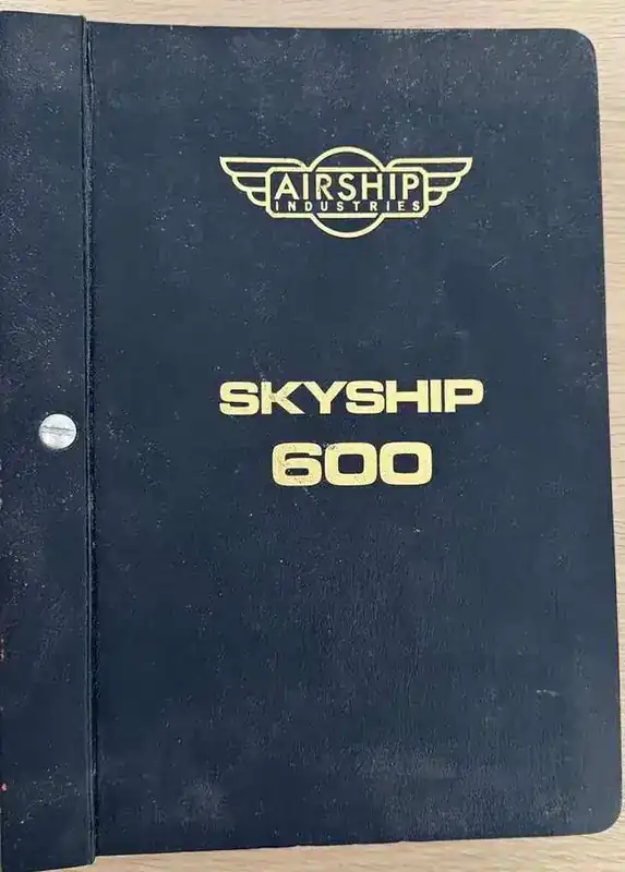
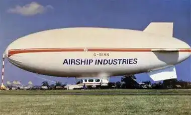
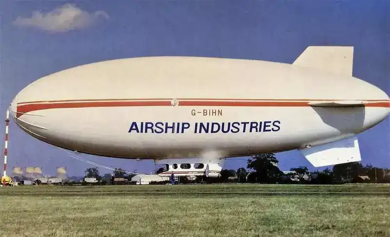
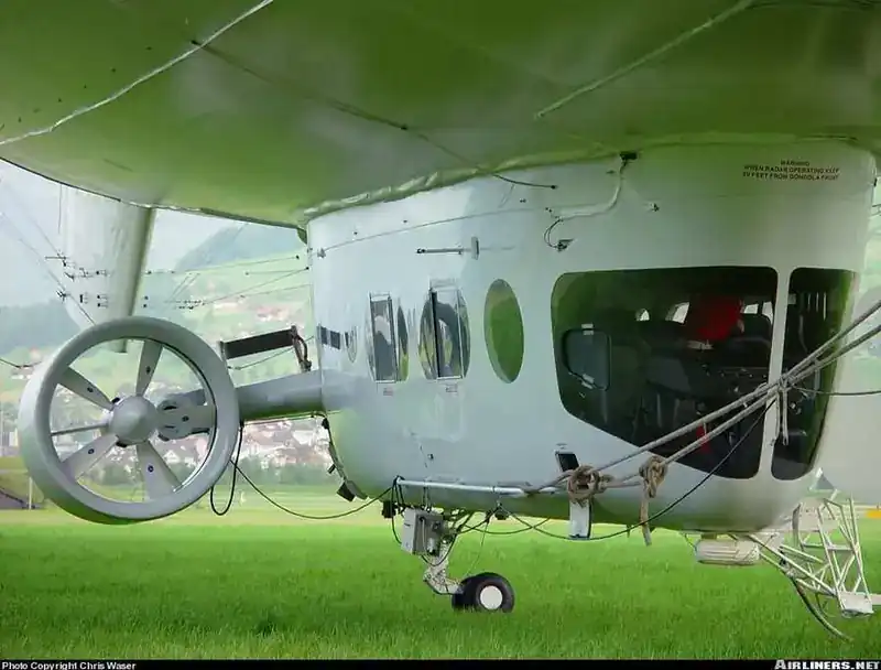
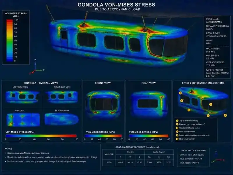
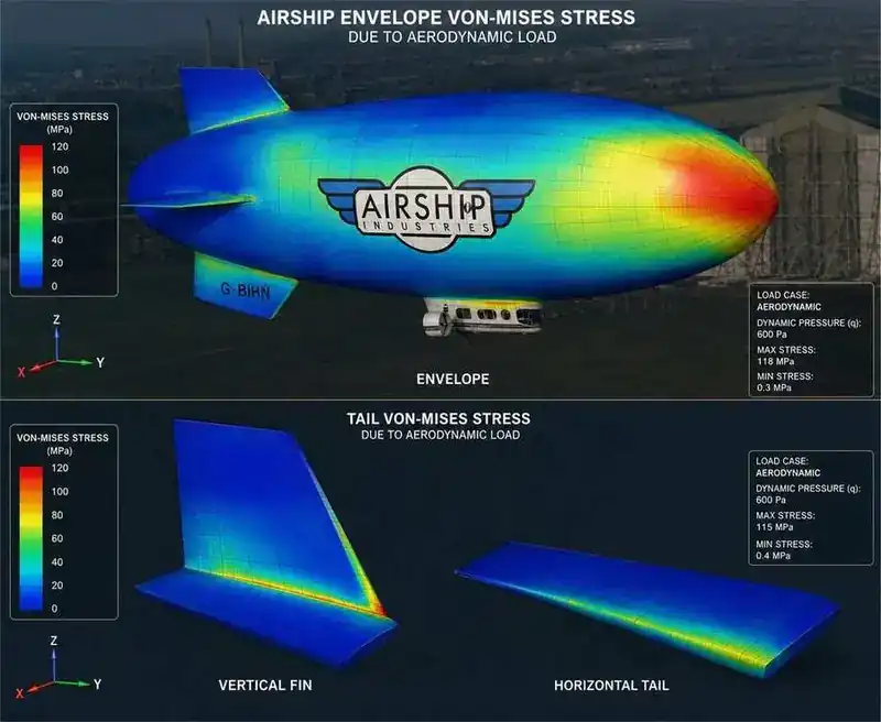
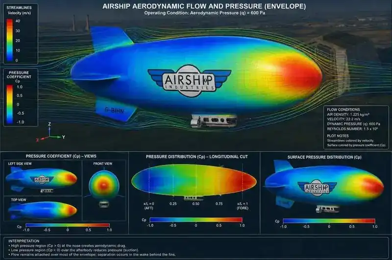
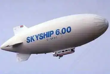
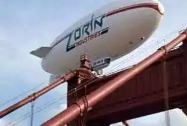
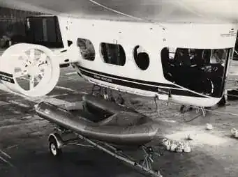
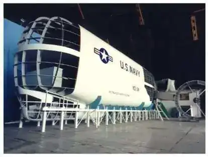
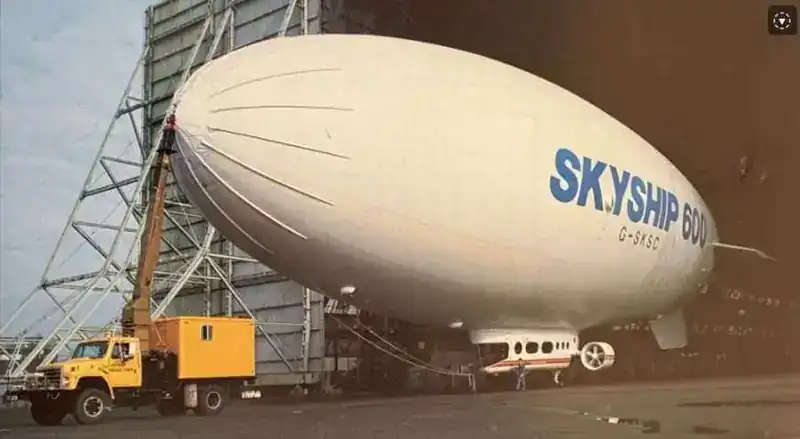
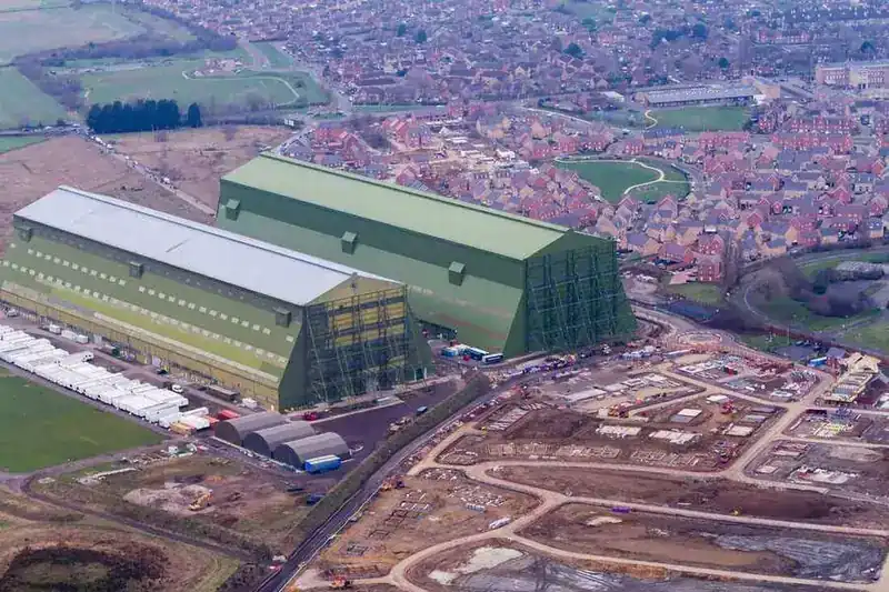
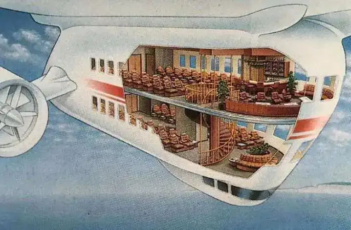
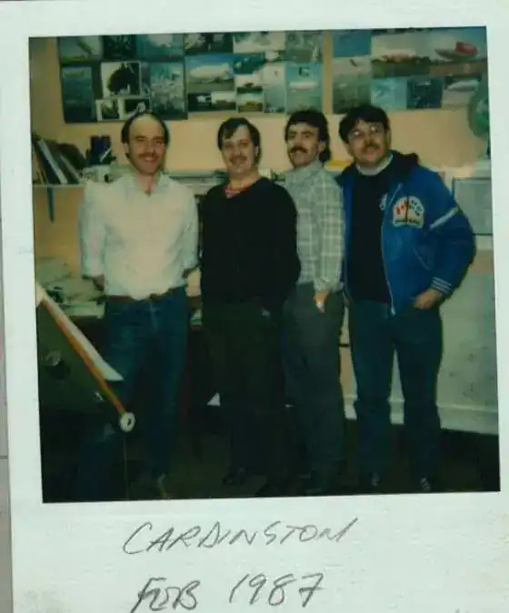
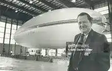
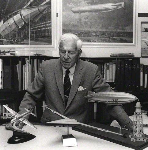
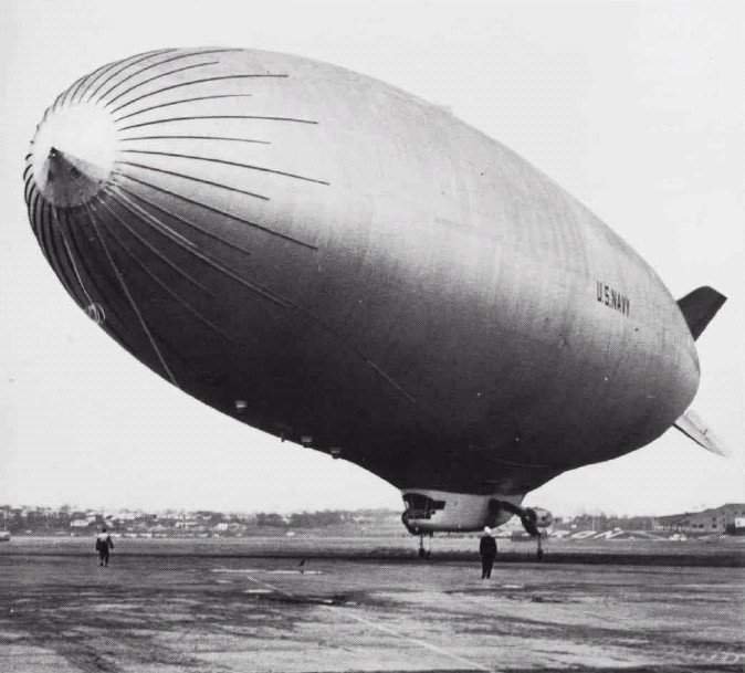
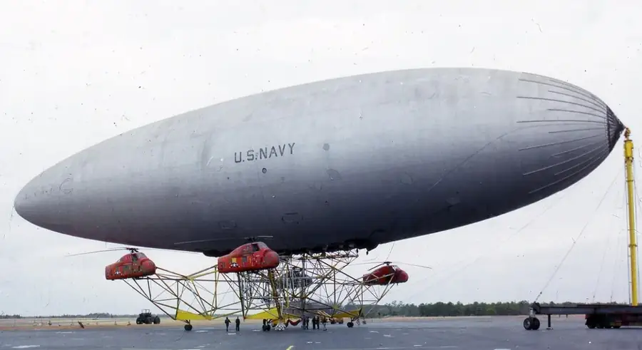
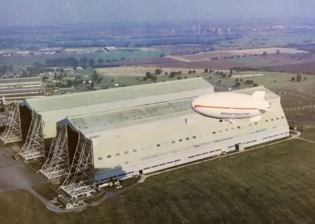
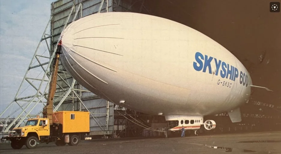
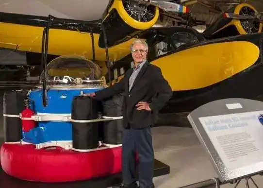
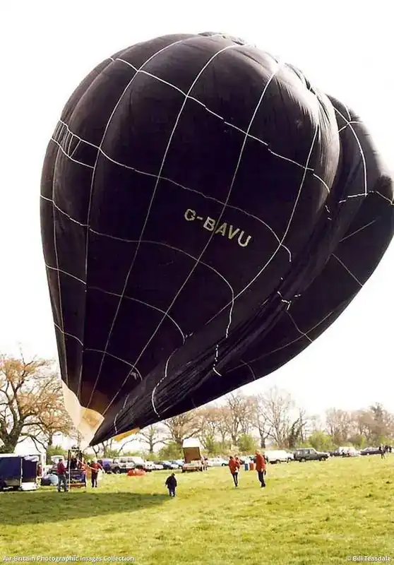

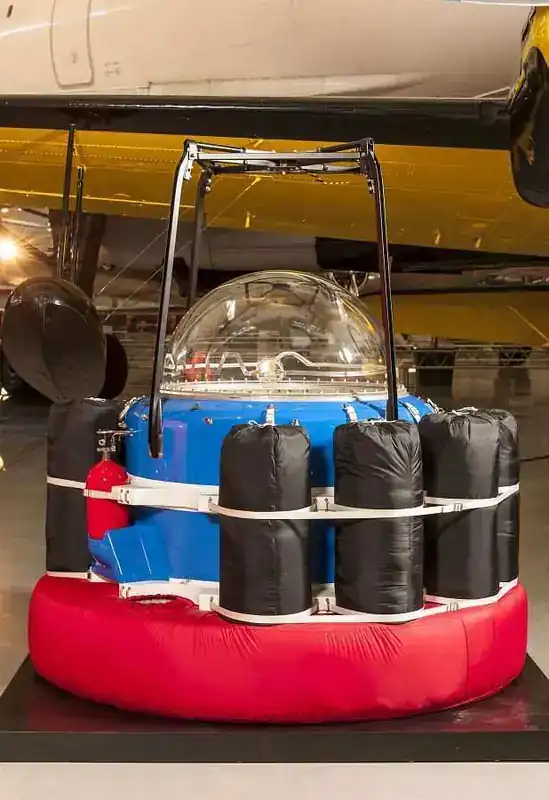
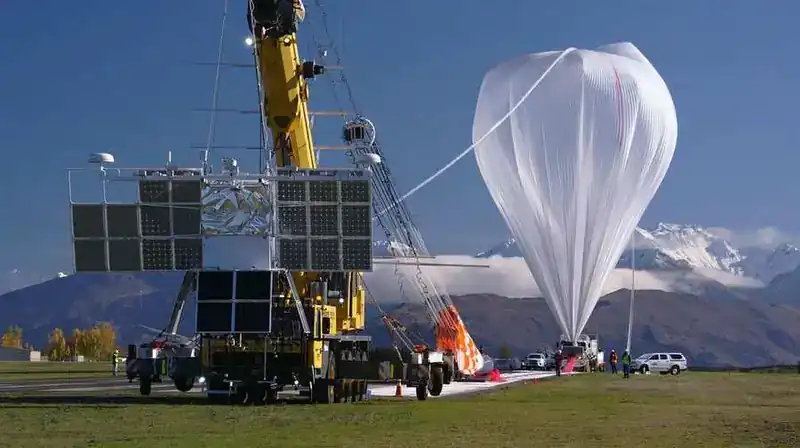
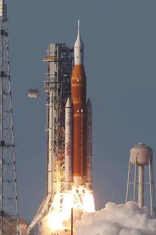
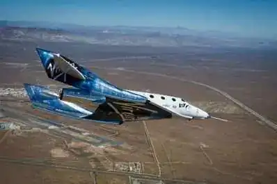
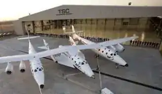
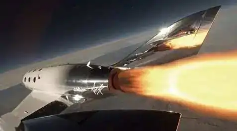
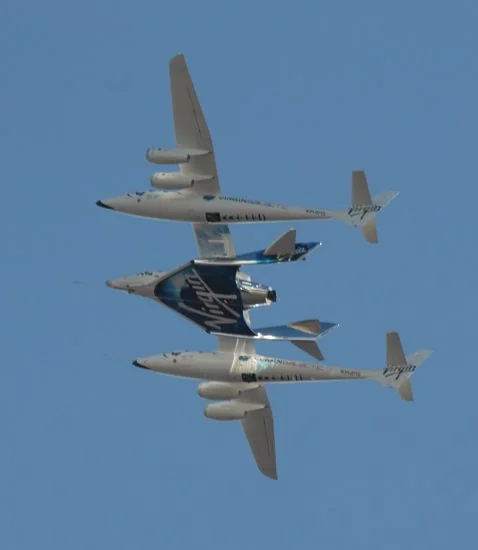
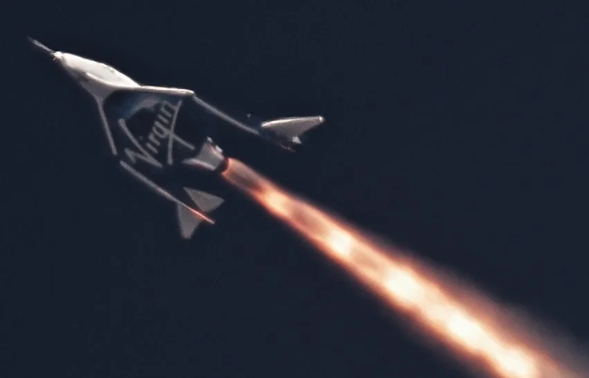
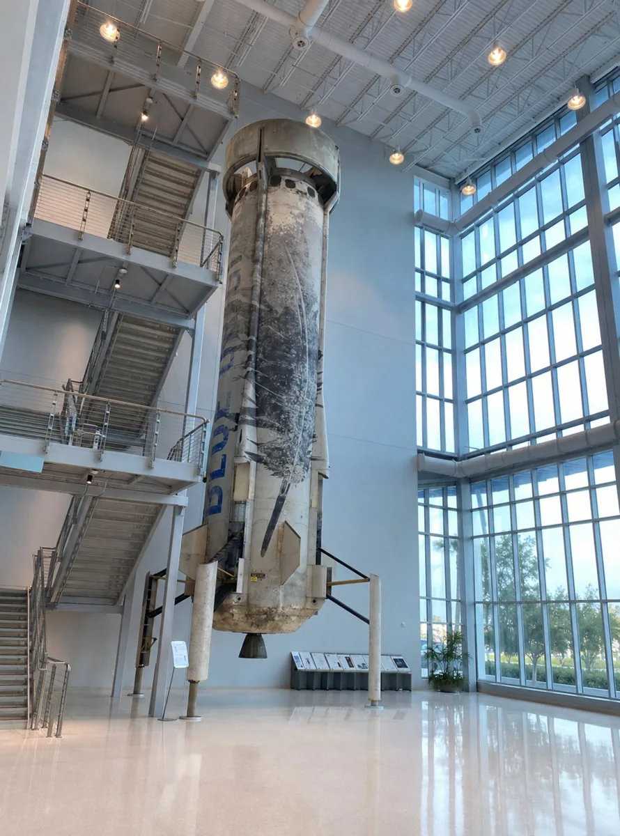
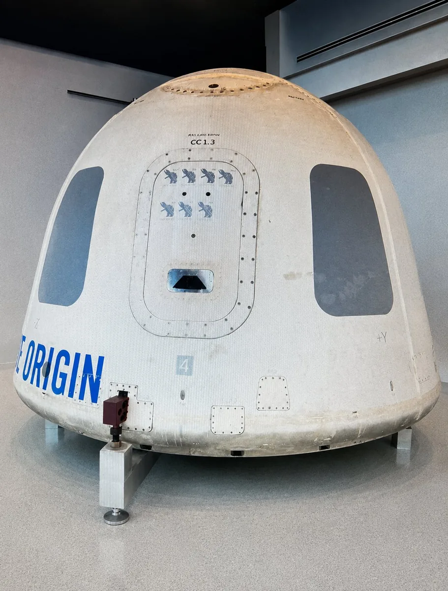
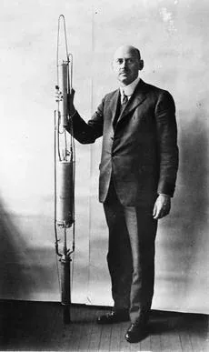
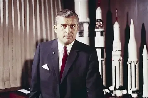
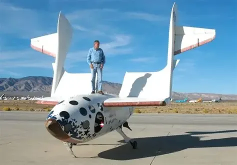




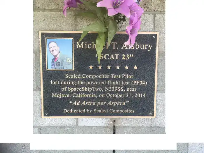
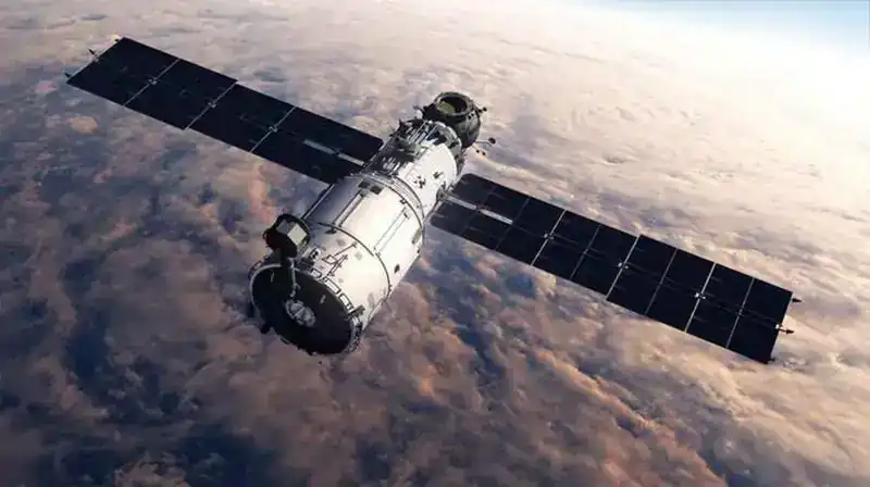
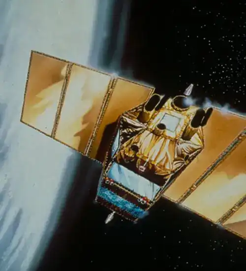
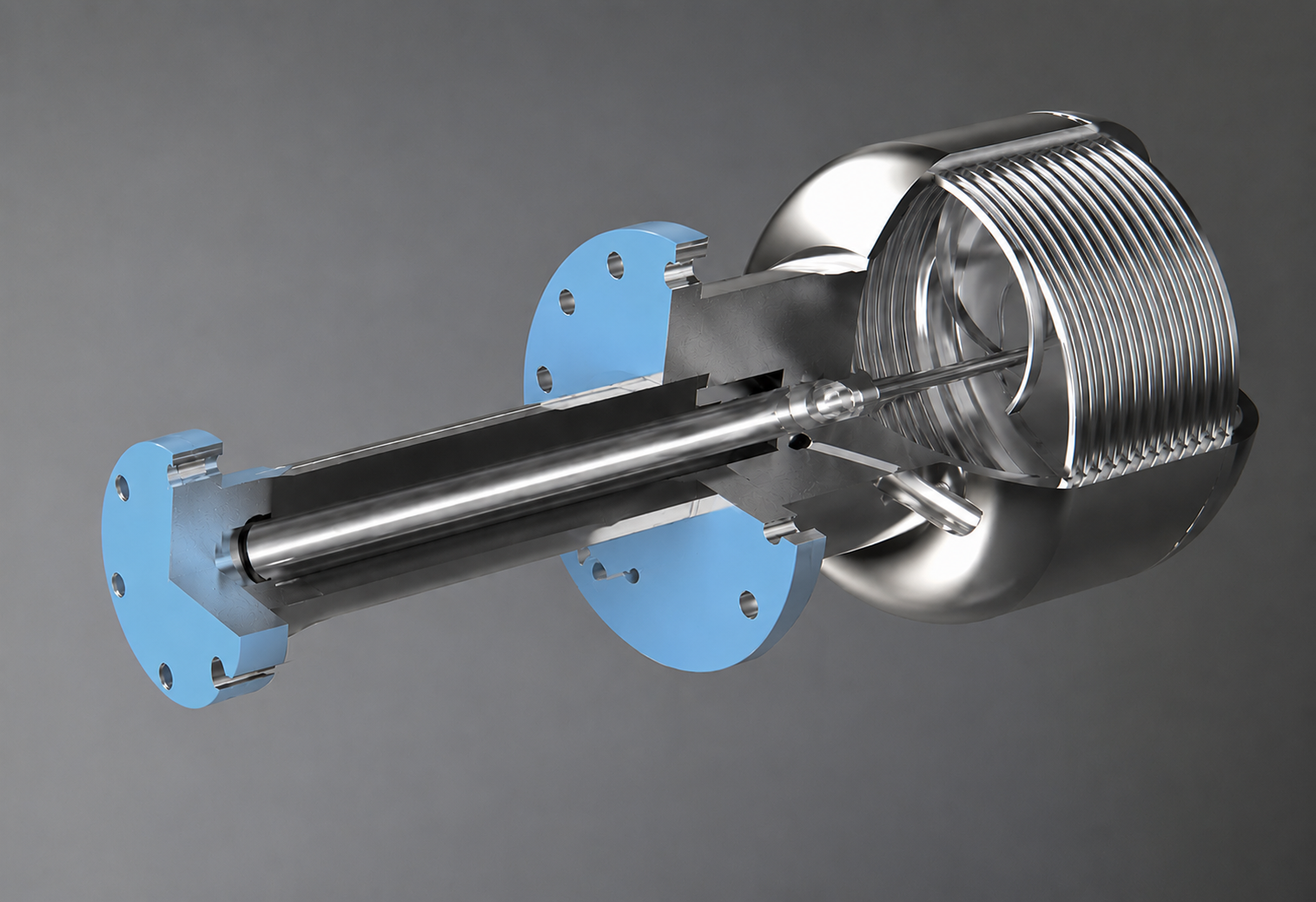
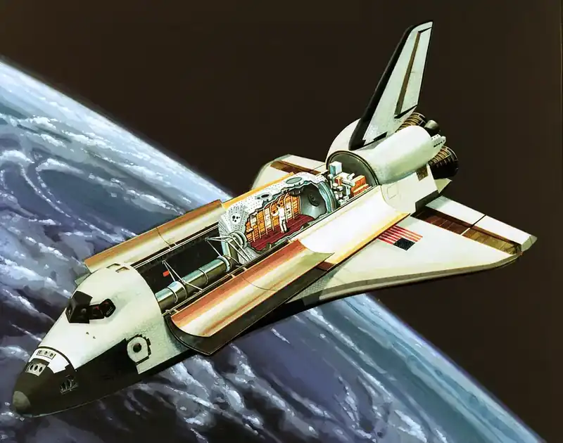
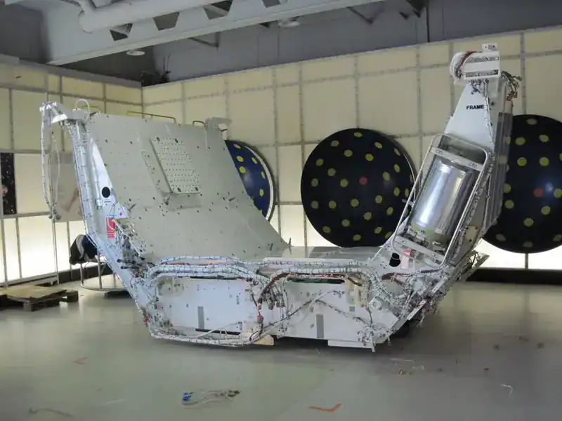
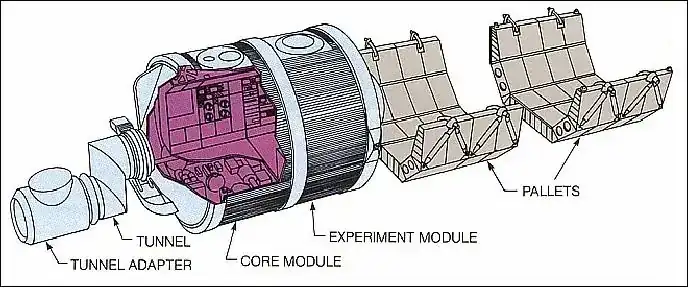
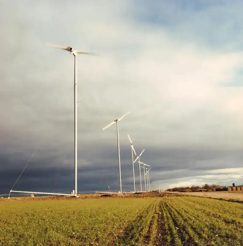
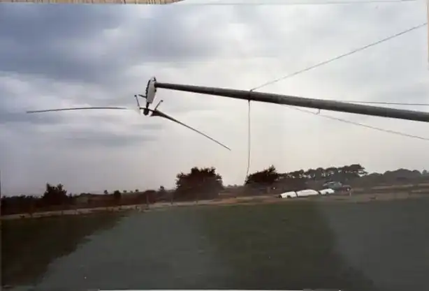
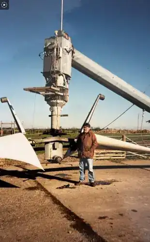
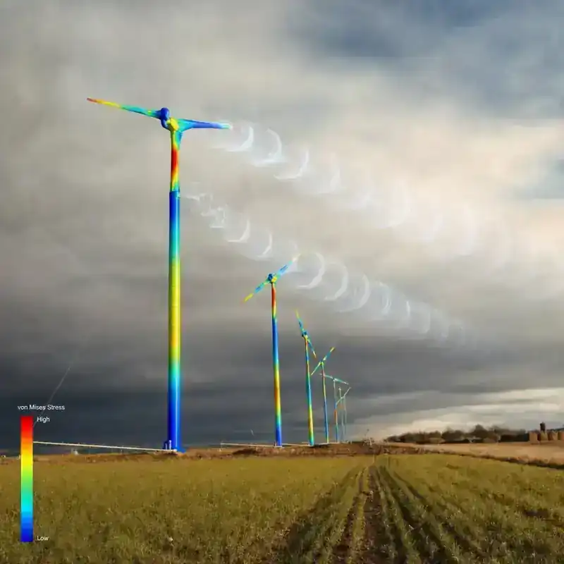
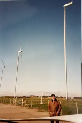
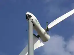



 www.arizonafuels.com